
High-density modular magnetic torquer applied to micro-nano satellite and design method

A magnetic torque device and micro-nano-satellite technology, applied in the direction of aerospace vehicle guidance devices, etc., can solve the problems of large number of circuit boards, complex cables, equipment impact, etc., achieve high density and integration, reduce launch costs, and facilitate installation Effect

Inactive Publication Date: 2017-12-12
CHANGCHUN INST OF OPTICS FINE MECHANICS & PHYSICS CHINESE ACAD OF SCI
View PDF5 Cites 4 Cited by
  • Summary
  • Abstract
  • Description
  • Claims
  • Application Information

AI Technical Summary

Problems solved by technology

[0004] The present invention aims to solve the problems of large size, complicated cables, and too many circuit boards involved in existing on-board magnetic torque devices, which lead to impacts on other devices on the satellite, and provides a high-speed magnetic torque device applied to micro-nano satellites. Density Modular Magnetic Torquer

Method used


Image

  • High-density modular magnetic torquer applied to micro-nano satellite and design method
  • High-density modular magnetic torquer applied to micro-nano satellite and design method
  • High-density modular magnetic torquer applied to micro-nano satellite and design method

Examples


specific Embodiment approach 1

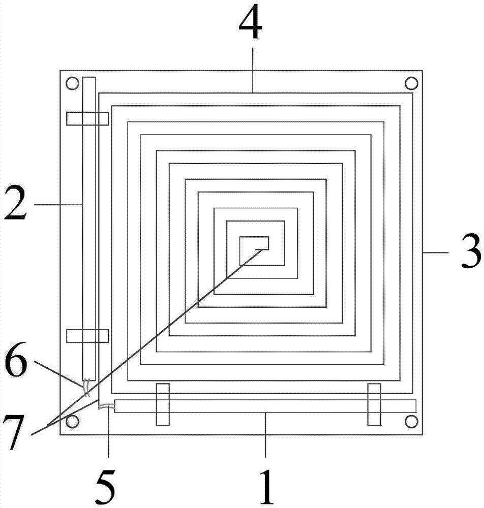
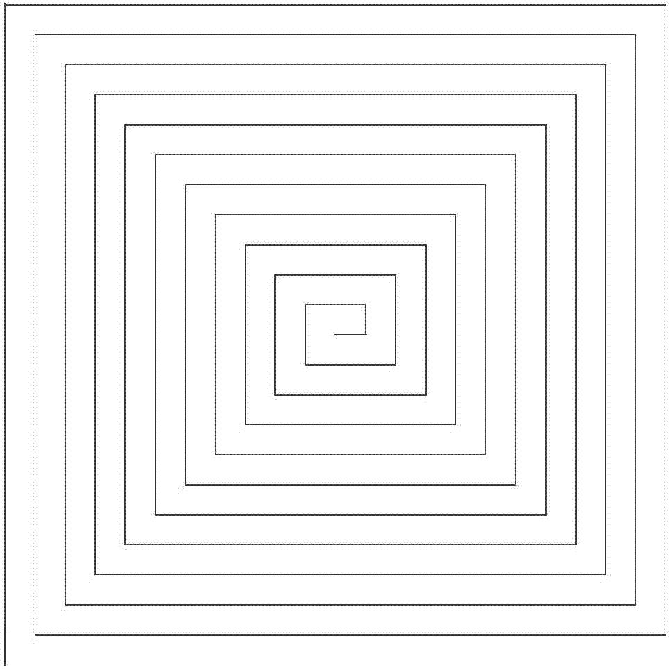
[0017] Specific implementation mode 1. Combination Figure 1 to Figure 4 Describe this embodiment, a high-density modular magnetic torque device applied to micro-nano satellites, including X-axis magnetic rod 1 and Y-axis magnetic rod 2, Z-axis hollow magnetic torque device 4, and a three-axis magnetic torque device control and drive circuit board (PCB board) 3, the X-axis magnetic bar 1 and the Y-axis magnetic bar 2 are vertically installed on the plane of the PCB board 3 . The coil input end and output end 5 of the X-axis magnetic bar 1 , the coil input end and output end 6 of the Y-axis magnetic bar 2 , and the coil input end and output end 7 of the Z-axis hollow magnetic torque device 4 are connected to the PCB board 3 . The PCB board 3 includes a three-axis magnetic torque device control and drive circuit, and the three-axis magnetic torque device control and drive circuit includes a main control chip, an AD sampling circuit, a communication circuit, a three-way H-bridge ...

specific Embodiment approach 2

[0019] Specific embodiment 2. This embodiment is the design method of the high-density modular magnetic torque device applied to the micro-nano satellite described in the specific embodiment 1. The method is realized by the following steps:

[0020] Step 1. According to the magnetic control requirements of micro-nano satellites, obtain the same magnetic moment index of the X-axis magnet bar and the Y-axis magnet bar, that is, M xy 1Am 2 , according to the magnetic moment index M of the X-axis magnetic rod and the Y-axis magnetic rod xy , design the X-axis magnetic rod and the Y-axis magnetic rod to have the same length and diameter, that is, the length L of the magnetic rod is 9cm and the diameter d is 6mm, M xy The formula is expressed as:

[0021] In the formula, B is the average magnetic flux density in the rod core, V is the volume of the magnetic rod, μ is the effective magnetic permeability of the magnetic rod, N xy is the total number of turns of the magnetic bar c...


PUM


Abstract

The invention provides a high-density modular magnetic torquer applied to a micro-nano satellite and a design method, and relates to the field of control of magnetic torquers. The problems that the existing on-satellite magnetic torquer is large in size, complex in cables and excessive in circuit boards involved, and thus other on-satellite devices are affected are solved. The magnetic torquer comprises an X-axis magnetic bar, a Y-axis magnetic bar, a Z-axis hollow magnetic torquer and a PCB. The X-axis magnetic bar and the Y-axis magnetic bar are perpendicularly mounted on the PCB. The hollow magnetic torquer is composed of a hollow square coil and integrated on the PCB. The length and diameter of the X-axis magnetic bar and the length and diameter of the Y-axis magnetic bar are obtained according to magnetic torque indexes of the X-axis magnetic bar and the Y-axis magnetic bar; the size of the PCB is determined; the length and width, on the PCB, of the trace of the Z-axis hollow magnetic torquer are further obtained; finally the Z-axis hollow magnetic torquer is arranged on the PCB, and thus the design of the modular magnetic torquer is realized. The method has the advantages of high operability, simple external interfaces, and simplification of on-satellite cables, and the launching cost of the satellite is greatly reduced.

Description

technical field [0001] The invention relates to the field of magnetic torque device control, in particular to a high-density modular magnetic torque device. Background technique [0002] Due to their small size, light weight, and low cost, micro-nano satellites are widely used in space missions. As one of its most important attitude control actuators, the magnetic torquer with small volume, large magnetic moment and high density has also become a research hotspot. [0003] At present, it is known that the magnetic torquer used by the micro-nano satellite has the following forms: one air-core coil and two soft magnetic core rods, three soft magnetic core magnetic rods or three sets of PCB boards. Among them, the first two forms are larger in size, heavier in weight, and have high launch costs. The latter is a magnetic torquer in the form of three sets of PCB boards. Each circuit board must lead out the magnetic torquer wiring, which makes the cable on the star too complicate...

Claims


Application Information

Patent Timeline
Patent Type & Authority Applications(China)
IPC IPC(8): B64G1/24B64G1/28
Inventor 周美丽朴永杰张贵祥常琳章家保冯汝鹏
Owner CHANGCHUN INST OF OPTICS FINE MECHANICS & PHYSICS CHINESE ACAD OF SCI
Learn More