A cable insulator thermal breakdown voltage determining method and device

A technology for cable insulation and determination methods, applied in the direction of testing dielectric strength, etc., can solve problems affecting power transmission safety, inaccurate evaluation of thermal breakdown conditions, etc.

Active Publication Date: 2017-12-12
GLOBAL ENERGY INTERCONNECTION RES INST EURO GMBH +3
View PDF7 Cites 5 Cited by
  • Summary
  • Abstract
  • Description
  • Claims
  • Application Information

AI Technical Summary

Problems solved by technology

[0005] Therefore, the technical problem to be solved by the present invention is that in the prior art, the evaluation of the thermal breakdown of the cable insulation is not accurate, which affects the safety of power transmission.

Method used


Image

  • A cable insulator thermal breakdown voltage determining method and device
  • A cable insulator thermal breakdown voltage determining method and device
  • A cable insulator thermal breakdown voltage determining method and device

Examples


Embodiment 1

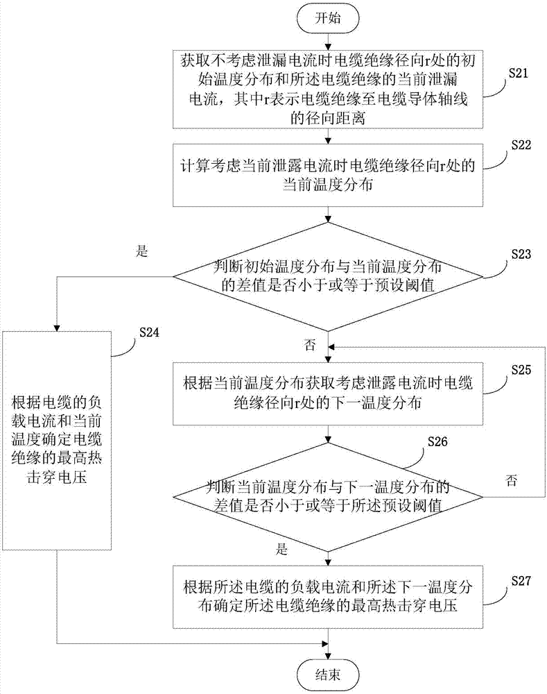
[0083] This embodiment provides a method for determining the thermal breakdown voltage of cable insulation, which is suitable for evaluating the thermal breakdown of various cables, such as figure 2 As shown, the method includes the following steps:

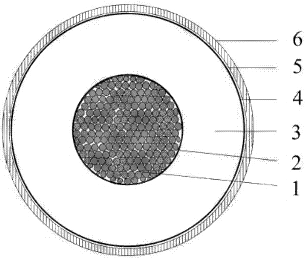
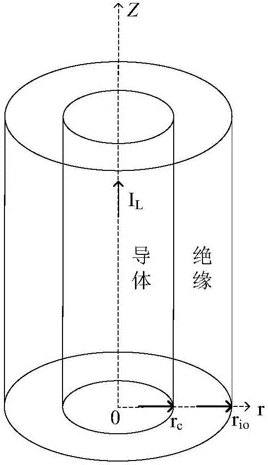
[0084] S21: Obtain the initial temperature distribution at the radial direction r of the cable insulation and the current leakage current of the cable insulation when the leakage current is not considered, where r represents the radial distance from the cable insulation to the axis of the cable conductor; here, the initial temperature distribution That is, in order to ignore the loss caused by the leakage current of the cable insulation, the initial temperature distribution at the radial direction r of the cable insulation is assumed under the condition that the temperature of the cable conductor and the metal sheath is constant. Specifically, when ignoring the structure outside the metal sheath of the DC cable, the structure of...

Embodiment 2

[0129] This embodiment provides a cable insulation thermal breakdown voltage determination device, such as Figure 4 As shown, the device includes: a first acquisition module 41, a calculation module 42, a first judgment module 43, a first determination module 44, a second acquisition module 45, a second judgment module 46, a repetition module 47 and a second determination module 48 , the main functions of each module are as follows:

[0130] The first acquisition module 41 is configured to acquire the initial temperature distribution at the radial direction r of the cable insulation and the current leakage current of the cable insulation when the leakage current is not considered, where r represents the radial distance from the cable insulation to the axis of the cable conductor; For details, refer to the detailed description of step S21 in Embodiment 1.

[0131] The calculation module 42 is configured to calculate the current temperature distribution at the radial direction...


PUM


Abstract

The invention provides a cable insulator thermal breakdown voltage determining method and device. The method comprises the steps of acquiring initial temperature distribution at a radial r position of a cable insulator without consideration of a leak current and a current leak current of the cable insulator, wherein r represents the radial distance from the cable insulator to the axis of a cable conductor; calculating a current temperature distribution at the radial r position of the cable insulator with consideration of the current leak current; judging whether the difference between the initial temperature distribution and the current temperature distribution is less than or equal to a preset threshold value; if the difference between the initial temperature distribution and the current temperature distribution is less than or equal to the preset threshold value, determining a maximum thermal breakdown voltage of the cable insulator according to a load current of the cable and the current temperature. The method and the device are based on direct current cable thermal field distribution and comprehensively takes into consideration the influence of load currents of cables and leak currents of cable insulators on a cable insulator thermal breakdown voltage, thereby being more accurate in cable thermal breakdown voltage assessment.

Description

technical field [0001] The invention relates to the technical field of power transmission, in particular to a method and device for determining thermal breakdown voltage of cable insulation. Background technique [0002] DC cables transmit electrical energy in the form of transmitting DC current. The stable operation performance of the DC cable in the DC transmission system is one of the main factors affecting the stable operation of the DC system. Such as figure 1 As shown, the DC cable includes cable conductor 1, conductor shield 2, cable insulation 3, insulation outer shield 4, water blocking buffer layer 5, metal sheath 6, etc. from inside to outside. The cable conductor 1 is used to transmit current; the conductor shield 2 is composed of a semi-conductive water-blocking tape and a semi-conductive shielding material, and its main function is to uniform the electric field; the insulating outer shield 4 is composed of a semi-conductive shielding material, and its main fu...

Claims


Application Information

Patent Timeline
Patent Type & Authority Applications(China)
IPC IPC(8): G01R31/12
CPCG01R31/12
Inventor 王海田周明瑜韩正一罗艺叶瀚宇雷宪章
Owner GLOBAL ENERGY INTERCONNECTION RES INST EURO GMBH
Why Eureka
Try Eureka