Multi-frequency and multi-beam MIMO antenna

A multi-beam and antenna technology, applied in the field of multi-frequency and multi-beam MIMO antennas, can solve the problems of poor practicability, large volume, complex structure of MIMO antennas, etc., and achieve good market prospects, enhanced gain, and low cost.

Active Publication Date: 2017-12-12
NANJING UNIV OF INFORMATION SCI & TECH
View PDF8 Cites 4 Cited by
  • Summary
  • Abstract
  • Description
  • Claims
  • Application Information

AI Technical Summary

Problems solved by technology

The MIMO antenna in the prior art has a complex str

Method used


Image

  • Multi-frequency and multi-beam MIMO antenna
  • Multi-frequency and multi-beam MIMO antenna
  • Multi-frequency and multi-beam MIMO antenna

Examples


Embodiment Construction

[0034] The present invention will be further described below in conjunction with the accompanying drawings. The following examples are only used to illustrate the technical solution of the present invention more clearly, but not to limit the protection scope of the present invention.

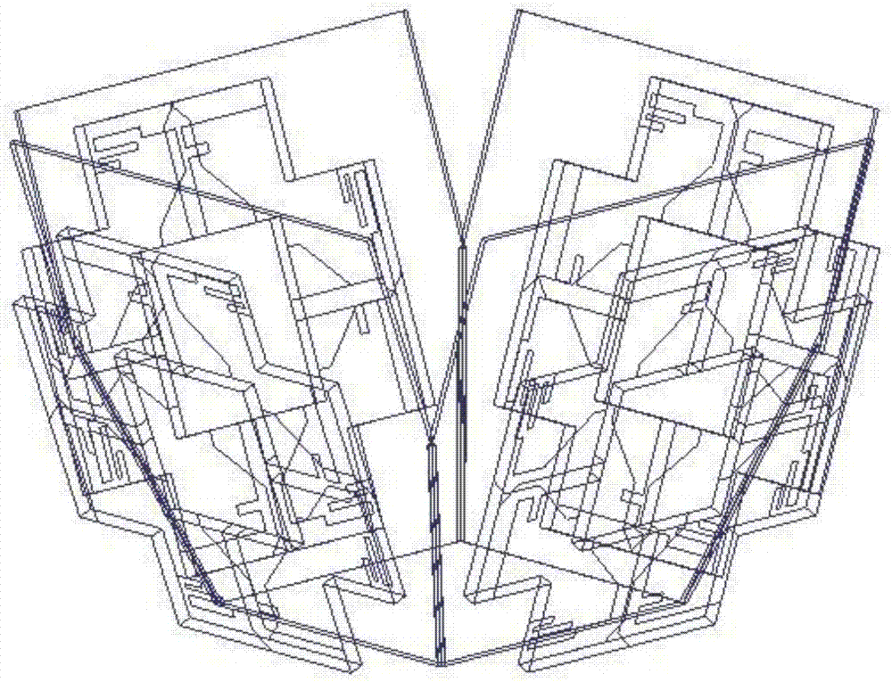
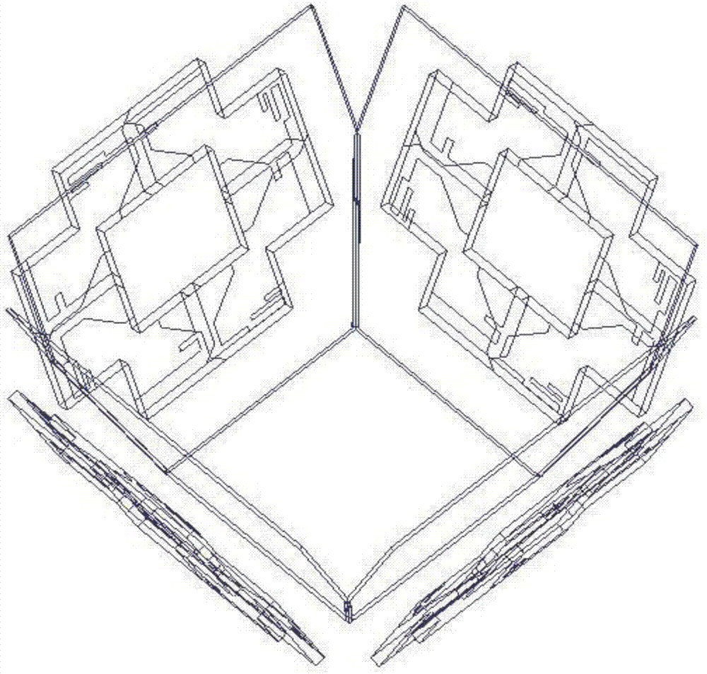
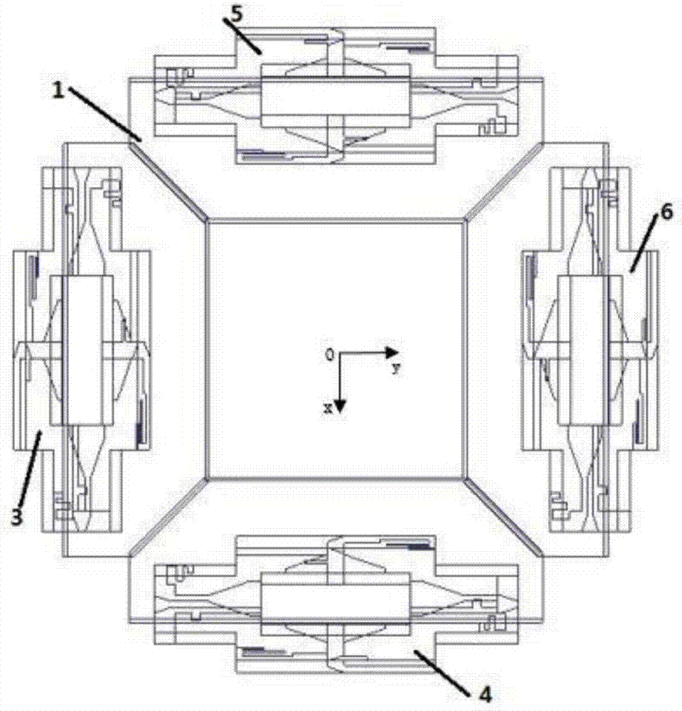
[0035] like Figure 1-Figure 4 As shown, a multi-frequency and multi-beam MIMO antenna includes several reflectors 1 and several MIMO units 2, and several reflectors 1 are connected to each other from end to end around the vertical axis along the circumferential direction, and several reflectors 1 are all away from each other. The direction of the vertical axis is inclined, and one MIMO unit is fixed parallel to the outside of each reflector, and the MIMO unit includes several dipole array elements 9, and several dipole array elements 9 surround The axes of the MIMO units are arranged in sequence along the circumferential direction.

[0036] Further, the present invention includes four reflecto...


PUM

PropertyMeasurementUnit
Angleaaaaaaaaaa

Abstract

The present invention relates to a multi-frequency and multi-beam MIMO antenna, pertaining to the technical field of antenna. The antenna comprises a plurality of reflecting plates (1) and a plurality of MIMO units (2). The reflecting plates (1) are successively connected with each other end-to-end around the vertical axis along the circumferential direction, the reflecting plates (1) all lean towards the direction far away from the vertical axis, and the outside of every reflecting plate is fixedly provided with one MIMO unit parallelly. Every MIMO unit comprises a plurality of dipole array elements (9), and the dipole array elements (9) are successively arranged around the axis of the MIMO unit along the circumferential direction. According to the multi-frequency and multi-beam MIMO antenna applied in WLAN/WiMAX wireless communication, beams generated by four MIMO units turn towards different directions, reflecting that the device has the characteristic of diversity of the directional diagram, indicating that the device can generate four directional beams, and meeting the energy demand of different directions. The antenna has the advantages of antenna miniaturization, low space occupation and easiness for installation.

Description

technical field [0001] The invention relates to a multi-frequency and multi-beam MIMO antenna, belonging to the technical field of antennas. Background technique [0002] Nowadays, wireless communication technology is developing rapidly, and the requirements for wireless communication speed and communication quality are increasing day by day. Multi-beam technology can realize beam isolation, frequency reuse, and improve communication capacity; MIMO technology uses multiple antennas to transmit and receive signals, which can increase data transmission rate and communication quality. WLAN / WiMAX wireless communication generally hopes to cover frequency bands of 2.4GHz-2.48GHz, 3.4GHz-3.7GHz, and 5.15GHz-5.85GHz, and requires high gain. The structure of the MIMO antenna in the prior art is complicated, the volume occupies a large space, and the practicability is not good. Contents of the invention [0003] The technical problem to be solved by the present invention is to ove...

Claims


Application Information

Patent Timeline
IPC IPC(8): H01Q21/00H01Q19/10H01Q5/10H01Q5/307H01Q5/50H01Q1/36H01Q1/52
CPCH01Q1/36H01Q1/52H01Q5/10H01Q5/307H01Q5/50H01Q19/106H01Q21/00Y02D30/70
Inventor 王友保肖顺韦叶
Owner NANJING UNIV OF INFORMATION SCI & TECH
Why Eureka
Try Eureka