
Battery control device and battery control system

A battery control and battery technology, applied in the direction of battery circuit devices, circuit devices, secondary batteries, etc., can solve problems such as unstable function operation, achieve the effect of enhancing monitoring and ensuring stability

Pending Publication Date: 2017-12-12
BEIJING NAT BATTERY TECH
View PDF6 Cites 4 Cited by
  • Summary
  • Abstract
  • Description
  • Claims
  • Application Information

AI Technical Summary

Problems solved by technology

However, the above functions of the BMS are not stable

Method used


Image

  • Battery control device and battery control system
  • Battery control device and battery control system
  • Battery control device and battery control system

Examples


Embodiment 1

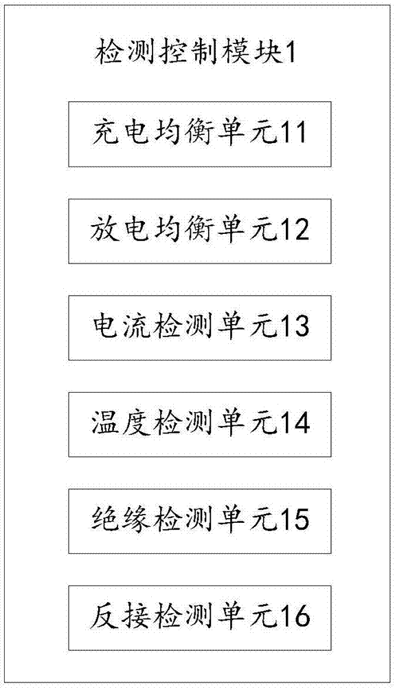
[0051] see figure 1 , figure 2 and image 3 , the battery control device 6 proposed in this embodiment specifically includes: a detection control module 1, a central processing unit 2 and a controller 3 connected in sequence, in the battery control device 6, the detection control module 1 is used for real-time monitoring of the battery pack to be tested 5 performance parameters, and the detection control module 1 can also convert the performance parameters into a performance monitoring signal and send it to the central processing unit 2, and then the central processing unit 2 is used to compare whether the performance monitoring signal is consistent with the pre-stored standard monitoring signal , and, when the comparison results are inconsistent, the central processing unit 2 generates a difference signal, and then the controller 3 is used to control the battery pack 5 to be tested after receiving the difference signal. What needs to be explained here is that in the actual...

Embodiment 2

[0066] see Figure 4 , the present embodiment provides a battery control system including: a battery pack 5 and the above-mentioned battery control device 6, in the battery control system, the battery pack 5 and the battery control device 6 are electrically connected, and when in use, the battery control device 6 is used to control The battery pack 5 is tested, and the performance signal of the battery pack 5 obtained from the test is processed. What needs to be explained here is that the performance signals include overvoltage, undervoltage, overcurrent, short circuit, reverse connection and so on.

[0067] To sum up, the battery control system provided by this embodiment includes: a battery pack 5 and the above-mentioned battery control device 6. In this battery control system, the battery pack 5 and the battery control device 6 are electrically connected. During operation, the battery control device 6 is used to test the battery pack 5 and process the performance signal ob...


PUM


Abstract

The invention provides a battery control device and a battery control system and relates to the technical field of batteries. The battery control device comprises a detection control module, a central processing unit and a controller which are sequentially connected. In the battery control device, the detection control module is used for monitoring performance parameters of a to-be-tested battery pack in real time and also can convert the performance parameters into a performance monitoring signal and transmit the performance monitoring signal to the central processing unit, then the central processing unit is used for comparing whether the performance monitoring signal is consistent with a prestored standard monitoring signal or not, and generating a difference signal when a comparison result is inconsistency, and then the controller is used for controlling the to-be-tested battery pack after receiving the difference signal. By virtue of the way, the performance of the to-be-tested battery pack can be comprehensively detected, so that the stability of the to-be-tested battery pack is enhanced.

Description

technical field [0001] The invention relates to the field of battery technology, in particular to a battery control device and system. Background technique [0002] With the development of electronic and electrical technology and the higher requirements of modern automobiles for fuel consumption, efficiency, and environmental protection, the 48V system (that is, the 48V electrical system) will bring changes to the automotive industry. Compared with the traditional 12V system, the 48V system can effectively improve The efficiency of the motor, in the application of the engine start-stop technology, is more extensive than the previous basic start-stop system, and has a better user experience. At the same time, the 48V system can more effectively recover the brakes of the car compared with the 12V system. Energy, while providing energy for the ever-changing automotive electrical appliances, it increases the fuel saving rate by about 10%. The 48V system will become the trend of ...

Claims


Application Information

Patent Timeline
Patent Type & Authority Applications(China)
IPC IPC(8): H02J7/00H01M10/42H01M10/48
CPCH02J7/0021H02J7/0091H01M10/4207H01M10/4257H01M10/48H02J7/0014H01M2010/4271Y02E60/10
Inventor 罗洪旭南金瑞姜新路刘志超
Owner BEIJING NAT BATTERY TECH
Learn More