Indoor visible light positioning method based on color space intensity distribution

A technology of color space and positioning method, applied in the direction of service, positioning, free space transmission based on location information, etc., can solve the problems of complex process and high demand for measurement data accuracy.

Active Publication Date: 2017-12-12
BEIJING UNIV OF POSTS & TELECOMM
View PDF7 Cites 13 Cited by
  • Summary
  • Abstract
  • Description
  • Claims
  • Application Information

AI Technical Summary

Problems solved by technology

[0007] The present invention aims at the problem that the accuracy of the measurement data between the point to be measured and the observation point in the measurement process proposed above is very high, and the process of calculating the specific positioning result by algorithm mapping from the measured value is too complicated, and proposes a method based on The indoor visible light positioning method based on the color space intensity distribution is simple and easy to deploy, with fast positioning speed and high precision; through cooperative control of the emission patterns of multiple visible light sources, the color space intensity distribution is constructed in the entire space area to achieve fast speed in the indoor visible light environment. Convenient location

Method used


Image

  • Indoor visible light positioning method based on color space intensity distribution
  • Indoor visible light positioning method based on color space intensity distribution
  • Indoor visible light positioning method based on color space intensity distribution

Examples


Embodiment Construction

[0089] The specific implementation method of the present invention will be described in detail below in conjunction with the accompanying drawings.

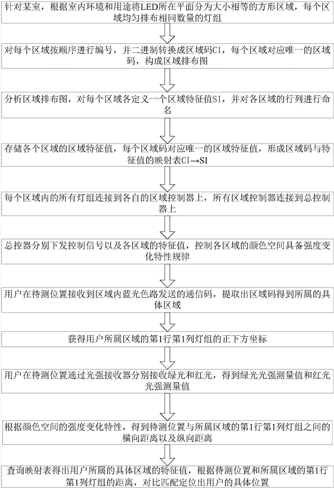
[0090] The present invention constructs a color space intensity distribution in the entire space area by cooperatively controlling the emission patterns of multiple visible light sources, so as to realize fast and convenient positioning in an indoor visible light environment. Assume that all LED light groups have the same properties; the receiver can receive the code pattern and light intensity (illuminance), such as figure 1 As shown, the specific steps are as follows:

[0091] Step 1. For a room, divide the plane where the LEDs are located into square areas of equal size according to the indoor environment and usage, and arrange the same number of light groups evenly in each area;

[0092]First, divide the number of areas and the number of light groups in the area according to the brightness of light required by the user and t...


PUM


Abstract

The invention discloses an indoor visible light positioning method based on the color space intensity distribution, and belongs to the field of the indoor visible light positioning. The method is specifically as follows: firstly dividing a lamp band region of one room to construct a region layout diagram; and then defining each region feature value, and performing line-rank naming on each region to construction a mapping table of the region code and the feature value; performing the light intensity change control of three colors of red, green and blue on each region and each line-rank by a master controller, wherein the user performs the following operations: firstly determining a belonged specific region according to a blue light path at a to-be-measured location; and then respectively receiving a green light intensity measurement value and a red light intensity measurement value; computing the cross range and the longitudinal distance between the to-be-measured location and the first line and the first rank of each region; performing contrastive matching according to the mapping table to position the specific location of the user. By using the indoor visible light positioning method disclosed by the invention, the location position is contained in the light intensity information of the color space, thereby realizing the fast and convenient positioning under the indoor visible light environment, and the method has strong operability.

Description

technical field [0001] The invention belongs to the field of indoor visible light positioning, in particular to an indoor visible light positioning method based on color space intensity distribution. Background technique [0002] With the development of wireless technology and mobile Internet, the importance of indoor positioning has become increasingly prominent in order to meet the needs of positioning navigation, public safety and emergency response, social networking and marketing in indoor environments. In addition to satellite positioning technology and cellular positioning technology with a wide range of applications, positioning technologies such as WIFI, Bluetooth, infrared, ultra-wideband and RFID have considerable applications in indoor positioning. [0003] Indoor visible light positioning technology, as an application of visible light communication technology in the field of indoor positioning, expands on the basis of using existing indoor lighting equipment to ...

Claims


Application Information

Patent Timeline
Patent Type & Authority Applications(China)
IPC IPC(8): H04B10/116H04B10/50H04W4/02G01S5/16
CPCG01S5/16H04B10/116H04B10/502H04W4/021
Inventor 黄治同王振方时鑫宇纪越峰
Owner BEIJING UNIV OF POSTS & TELECOMM
Why Eureka
Try Eureka