Method and device for determining azimuth angle of base station antenna

A base station antenna and azimuth technology, which is applied in the field of wireless mobile network planning and optimization, can solve the problems of low accuracy of azimuth parameter values, no consideration of distribution, poor coverage, etc., and achieve the effect of improving efficiency and high parameter setting accuracy.

Active Publication Date: 2017-12-12
HANDAN BRANCH OF CHINA MOBILE GRP HEBEI COMPANYLIMITED
View PDF8 Cites 24 Cited by
  • Summary
  • Abstract
  • Description
  • Claims
  • Application Information

AI Technical Summary

Problems solved by technology

[0018] 1) The accuracy of the azimuth parameter value is low
The parameter value of the antenna azimuth angle depends on the simulation accuracy of the network planning, and the simulation accuracy is limited by the map accuracy and the propagation model, and usually has a large error with the actual situation, so the parameter value of the azimuth angle of the base station antenna does not meet the expected coverage scope
[0019] 2) It will reduce the network coverage efficiency
Because the network planning simulation does not consider the actual traffic distribution of the existing network, and only meets the goal of network coverage, the main coverage direction of the base station antenna will deviate from the traffic concentration area, resulting in no coverage or poor coverage in places where traffic needs to be concentrated; Areas with less traffic or no traffic have good coverage, which reduces network coverage efficiency and wastes coverage resources

Method used


Image

  • Method and device for determining azimuth angle of base station antenna
  • Method and device for determining azimuth angle of base station antenna
  • Method and device for determining azimuth angle of base station antenna

Examples


no. 1 example

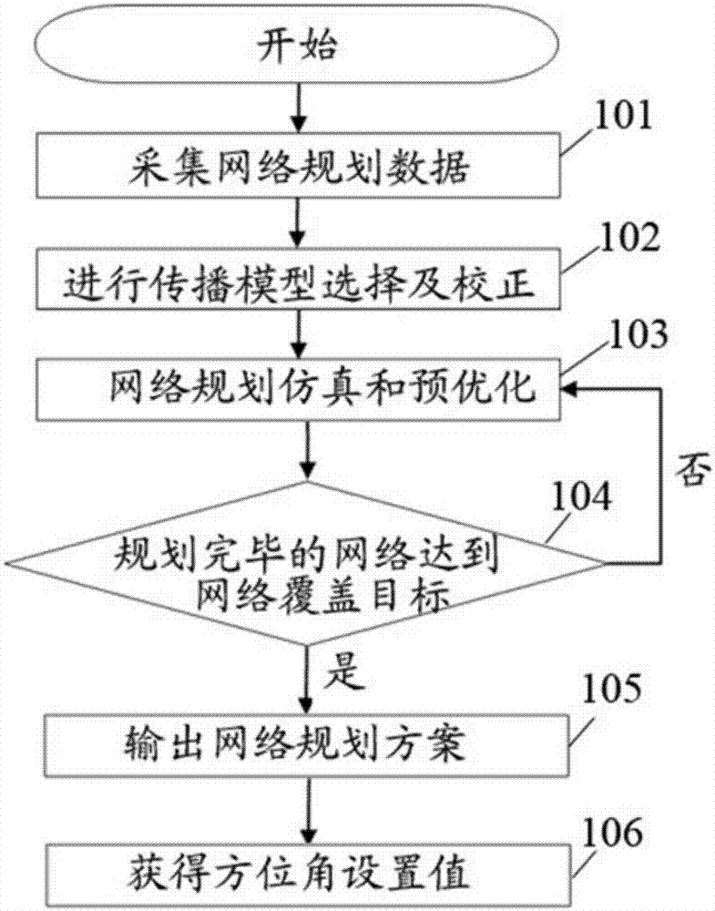
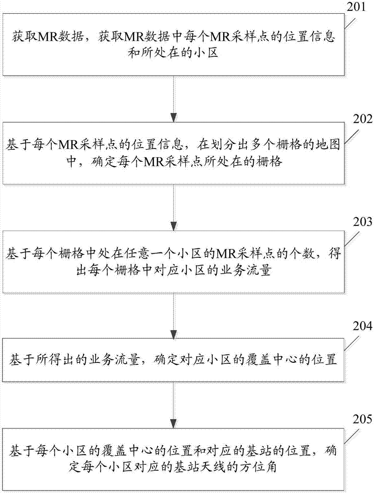
[0053] figure 2 A flowchart of a method for determining the azimuth angle of a base station antenna according to an embodiment of the present invention, as shown in figure 2 As shown, the process includes:

[0054] Step 201: Obtain measurement report (MR, Measurement Report) data, and obtain the location information and the cell where each MR sampling point is located in the MR data.

[0055] Here, the MR sampling point represents the location of the user equipment (UE, User Equipment); the cell where the MR sampling point is located represents the serving cell of the UE corresponding to the MR sampling point; In a Long Term Evolution (LTE, Long Term Evolution) system, the cell where the MR sampling point is located may represent the primary serving cell or the secondary serving cell of the UE corresponding to the MR sampling point.

[0056] In actual implementation, MR data can be obtained from a network management system (NMS, Network Management System); specifically, th...

no. 2 example

[0098] In order to better reflect the purpose of the present invention, further illustrations are made on the basis of the first embodiment of the present invention.

[0099] The second embodiment of the present invention provides a method for determining the azimuth angle of a base station antenna, which can be implemented by using a device for determining the azimuth angle of a base station antenna.

[0100] image 3 A schematic diagram of the first component structure of the device for determining the azimuth angle of the base station antenna according to the embodiment of the present invention, as shown in image 3 As shown, the device includes: data analysis module 301, MR positioning and grid module 302, grid evaluation module 303, coverage direction generation module 304, azimuth parameter value output module 305, the data analysis module 301, MR positioning The roles and functions of the grid module 302, the grid evaluation module 303, the coverage direction generatio...

no. 3 example

[0165] Regarding the method for determining the azimuth angle of the base station antenna in the first embodiment of the present invention, the third embodiment of the present invention proposes a device for determining the azimuth angle of the base station antenna.

[0166] Figure 7 A schematic diagram of the second component structure of the device for determining the azimuth angle of the base station antenna according to the embodiment of the present invention, as shown in Figure 7 As shown, the device includes: an acquisition module 701 and a determination module 702; wherein,

[0167] An acquisition module 701, configured to acquire the measurement report MR data, and acquire the location information and the cell where each MR sampling point is located in the MR data;

[0168] The determining module 702 is configured to determine the grid where each MR sampling point is located in a map divided into multiple grids based on the position information of each MR sampling p...


PUM


Abstract

The invention discloses a method and device for determining an azimuth angle of a base station antenna. The method comprises the following steps: obtaining MR data, and obtaining position information of each MR sampling point and a cell where each MR sampling point is located in the MR data; based on the position information of each MR sampling point, determining a grid where each MR sampling point is located in a map that is divided into a plurality of grids; based on the number of MR sampling points located in any cell in each grid, obtaining the service flow of the corresponding cell in each grid; based on the obtained service flow, determining the position of the coverage center of the corresponding cell; and based on the position of the coverage center of each cell and the position of the corresponding base station, determining the azimuth angle of the base station antenna corresponding to each cell.

Description

technical field [0001] The invention relates to the field of wireless mobile network planning optimization, in particular to a method and equipment for determining the azimuth angle of a base station antenna. Background technique [0002] As the upsurge of mobile Internet hits rural areas, the rural market has become a new growth blue ocean for mobile operators, and 4G network construction continues to extend to rural areas; however, due to the vast area of ​​rural areas, it is impossible for operators to build networks like cities In order to achieve high-density seamless coverage, it is necessary to ensure coverage of places where users are relatively concentrated during network coverage, so coverage optimization plays an important role. [0003] In coverage optimization, the azimuth angle of the base station antenna is a very important parameter. The azimuth angle of the base station antenna determines the main coverage direction of the cell; adjusting the azimuth angle o...

Claims


Application Information

Patent Timeline
Patent Type & Authority Applications(China)
IPC IPC(8): H04W16/18H04W24/02H04W24/10
CPCH04W16/18H04W24/02H04W24/10
Inventor 冯厚禄
Owner HANDAN BRANCH OF CHINA MOBILE GRP HEBEI COMPANYLIMITED
Why Eureka
Try Eureka