Cryogenic vial capable of being reversely rotated for rapid sampling and cryogenic box

A cryopreservation tube and cryopreservation box technology, which is applied in the field of medical experiments, can solve the problems of difficult removal of cell mixture and long thawing time, and achieve the effect of easy use, avoiding shaking, and rapid thawing and recovery of cells

Inactive Publication Date: 2017-12-15
FOURTH MILITARY MEDICAL UNIVERSITY
View PDF6 Cites 5 Cited by
  • Summary
  • Abstract
  • Description
  • Claims
  • Application Information

AI Technical Summary

Problems solved by technology

[0003] In view of the deficiencies in the prior art, the purpose of the present invention is to provide a reversible and rapid sampling cryopreservation tube and a cryopreservation box, which solves the difficulty in taking out the frozen cell mixture from the cryopreservation tube in the prior art, A technical issue that caused the unfreeze to take too long

Method used


Image

  • Cryogenic vial capable of being reversely rotated for rapid sampling and cryogenic box
  • Cryogenic vial capable of being reversely rotated for rapid sampling and cryogenic box
  • Cryogenic vial capable of being reversely rotated for rapid sampling and cryogenic box

Examples


Embodiment 1

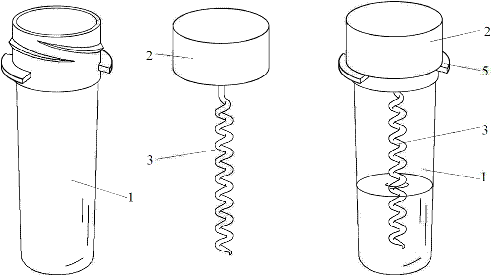
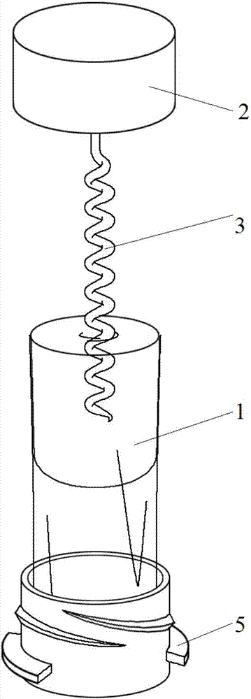
[0031] like Figure 1 to Figure 2 As shown, this embodiment provides a reversible rapid sampling cryopreservation tube, including a tube body 1, a sealing cap 2 and a stretching rod 3, one end of the stretching rod 3 is connected to the sealing cap 2, and the other end of the stretching rod goes deep into the Inside the tube body 1, the stretching rod 3 is in a spiral shape, and the sealing cover 2 is screw-mounted on one end of the tube body 1. The tube body here is a hard tube, and the other end of the tube body 1 is a soft film tube. The length accounts for about 3 / 4 of the total length of the tube body, and the cell fluid is placed in the soft film tube; the diameter of the tube body 1 gradually decreases from the opening of the tube body to the bottom of the tube body, and the angle between the side wall of the tube body and the axis of the tube body About 15°, the pipe body 1 is provided with a flange 5 .

Embodiment 2

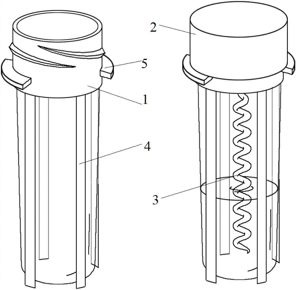
[0033] The difference between this embodiment and Embodiment 1 is that it further includes a fixing part 4, and the fixing part 4 extends from the top to the bottom of the soft film tube. The fixing part 4 is strip-shaped, and there are four fixing parts, which are evenly arranged along the circumference of the soft film tube. like image 3 shown.

Embodiment 3

[0035] like Figure 4 As shown, the present embodiment provides a reversible rapid sampling cryopreservation box, including a box body 6, the box body 6 is closed, and a plurality of through holes 7 are provided on one end surface of the box body 6, and a plurality of through holes 7 are arranged around the through holes 7. There is a limiting groove 8, and the limiting groove 8 is arranged along the edge of the through hole 7, so that the cryopreservation tube is firmly placed in the box body. The shape of the limiting groove 8 matches the shape of the flange 5 on the tube body of the freezing tube.


PUM


Abstract

The invention provides a cryogenic vial capable of being reversely rotated for rapid sampling and a cryogenic box. The cryogenic vial comprises a tube body, a sealing cap, and a drawing rod, one end of the drawing rod is connected to the sealing cap, the other end of the drawing rod extends into the tube body, the drawing rod is helical, and the other end of the tube body is a flexible film tube. The cryogenic box comprises a box body, the box body is closed, one end surface of the box body is provided with a plurality of through holes, and the circumference of each through hole is provided with limit notches. As cells are thawed, frozen cell mixture is drawn out of the flexible film tube of the cryogenic vial by means of the drawing body, and the drawing body is cut off to directly put the frozen cell mixture into the cryogenic box; the box body of the cryogenic box is provided with the limit notches, ribs are correspondingly arranged on the cryogenic vial, the shape of the limit notch matches the shape of the rib on the cryogenic vial, consequently, the cryogenic vial can be stably placed in the cryogenic box, and the shaking of the cryogenic vial is prevented.

Description

technical field [0001] The invention belongs to the field of medical experiments, relates to the cryopreservation of cell liquid, and in particular to a reversible and rapid sampling cryopreservation tube and a cryopreservation box. Background technique [0002] Under the ultra-low temperature below -70°C, the biochemical reactions inside the cells of organisms are extremely slow, or even terminated. Therefore, by taking appropriate methods to reduce biological materials to ultra-low temperature, life activities can be fixed at a certain stage without aging and death. When the cryopreserved biological material is returned to normal temperature in an appropriate way, the biochemical reactions inside it can return to normal. The so-called cryopreservation is to suspend in vitro cultures or bioactive materials in a solution with or without a cryoprotectant, and drop them to a certain temperature below zero at a certain freezing rate (usually an ultralow temperature below -70°C...

Claims


Application Information

Patent Timeline
Patent Type & Authority Applications(China)
IPC IPC(8): A01N1/02A01N3/00G01N1/42C12M1/24C12M1/00
CPCA01N1/0263A01N3/00G01N1/42C12M45/22
Inventor 费舟刘文博李兵胡世颉
Owner FOURTH MILITARY MEDICAL UNIVERSITY
Why Eureka
Try Eureka