Device for Freezing,Transporting and Thawing Fluids

a technology for transporting and thawing fluids, which is applied in the direction of fluid heaters, air heaters, stationary conduit assemblies, etc. it can solve the problems of inconvenient thawing process, inconvenient thawing, and insufficient thawing speed, so as to achieve rapid thawing, increase the number of operating options, and reduce the effect of thawing speed

Inactive Publication Date: 2009-12-17
ZETA BIOPHARMA
View PDF7 Cites 4 Cited by
  • Summary
  • Abstract
  • Description
  • Claims
  • Application Information

AI Technical Summary

Benefits of technology

[0008]Accordingly, the objective of this invention is to propose a device for freezing, transporting and thawing fluids, in particular sterile fluids, solutions and suspensions for the chemical, biotechnological, pharmaceutical and food industry, which does not have the disadvantages of the known devices and which permits a maximum amount of operating options. Another objective of the invention is to propose a device and a method whereby the frozen product can be thawed more rapidly and gently than in the past whilst simultaneously facilitating mixing of the thawed substrate.
[0009]These objectives are achieved by a device as defined in claim 1 and a method as defined in claim 10, by means of a heated immersion pipe which thaws at an early stage and therefore enables thawed and preferably pre-heated product to be pumped in circulation, i.e. drawn off and recirculated, during the entire thawing process. The disadvantages of the known methods are avoided and more rapid thawing is achieved.
[0010]The new device proposed by the invention has at least one immersion pipe which has an active thermal connection to the heat exchanger elements at least across a part-region of its longitudinal extension, which preferably extends from approximately a deepest point of the container as far as a maximum filling level. The maximum filling level is the filling level to which the container can be filled with product to be frozen and then thawed on a controlled basis. It is primarily defined by the position of the heat exchanger elements, making allowance for the expansion in volume caused by changes in density. In the case of the embodiments described below, it is between a top container edge and top portions of the heat exchanger elements. The immersion pipe is preferably in direct contact with at least one heat exchanger element and can be passively heated. During thawing, liquefied product can be drawn off from at least one heatable immersion pipe, which in turn preferably extends through the container interior from above and opens above a deepest point of the base. The heatable immersion pipe has an advantage over the known devices, in which the inlet pipe is disposed freely in the container interior and hence freely in the frozen product, because the frozen product thaws very rapidly in the interior of the immersion pipe and the process of drawing off the thawed liquid product is blocked only during an initial phase of the thawing process. Whilst it is being drawn off, the thawed product is also gently heated as it passes through the heated immersion pipe so that it can be discharged at a temperature significantly above freezing point, preferably from above, onto parts of the product still frozen and accelerates the thawing process. In a preferred embodiment of the invention, return pipes are provided on the internal face of the container lid for this purpose.
[0011]Heating the thawed product in the immersion pipe as it is drawn off offers a significant advantage over drawing it off from an outlet orifice in the base. In the case of a device of the type known from U.S. Pat. No. 5,524,706, the thawed product is drawn off through the bottom outlet and the product is at a temperature that is only just above freezing point. When this cold product is pumped through the filler neck onto the still frozen product, this barely accelerates the thawing process. In the case of the invention, the product pumped onto the still frozen parts is now pre-heated, which significantly speeds up the thawing process. Furthermore, drawing off the thawed product through the outlet orifice in the base is technically a disadvantage in terms of conductance.
[0012]Another advantage of the new device resides in the fact that the distance which the liquid product must travel as it is being pumped out of the container can be kept very short because it does not have to be directed from the outlet in the base to the inlet in the lid of the container. This obviates the need for undesirable pipes on the outside of the container on the one hand and discharging and emptying as well as pumping conveniently take place from the top of the new device on the other hand, because all connectors can be disposed in the lid or at least in a top region of the container.

Problems solved by technology

When this cold product is pumped through the filler neck onto the still frozen product, this barely accelerates the thawing process.
Furthermore, drawing off the thawed product through the outlet orifice in the base is technically a disadvantage in terms of conductance.

Method used


Image

  • Device for Freezing,Transporting and Thawing Fluids
  • Device for Freezing,Transporting and Thawing Fluids
  • Device for Freezing,Transporting and Thawing Fluids

Examples


Embodiment Construction

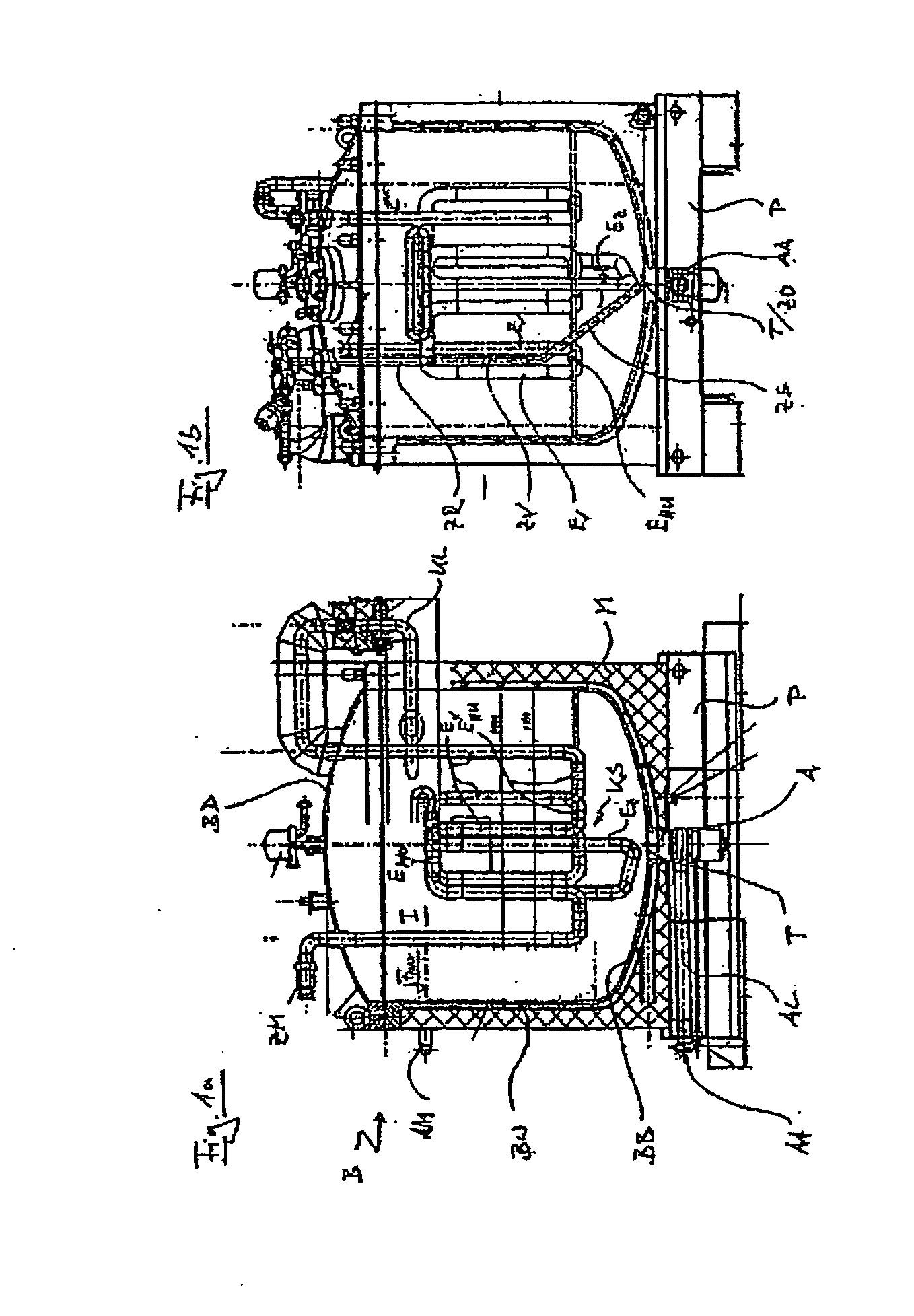
[0022]FIG. 1a is a longitudinal section illustrating a freeze-thaw container B designed by the applicant. As explained above, this container is known from the prior art under the name of FreezeContainer. The container B can be closed and sealed by means of a top lid BD. Together with a bottom base BB and a side wall BS, the lid BD defines an interior I of the container B, in which a cooling coil KS is disposed. As indicated in FIG. 1a, the cooling coil is connected so as to communicate with the double-skin inner container wall by means of an isolated cooling pipe KL. Coolant fed in through an appropriate inlet pipe AM to the double-skin container wall BW, flows through the container wall BW and base BB via the cooling pipe KL and is then directed through the cooling coil KS. It will be clear to the person skilled in the art that technically reversible processes of freezing and thawing can be effected using the device illustrated in FIG. 1 and with other similar generic devices on wh...


PUM


Abstract

The invention relates to a device (1) for freezing, transporting and thawing fluids, in particular sterile liquids, solutions and suspensions for the chemical, biotechnology, pharmaceutical and food industries. Said device comprises a container (10) with a lid (20), a wall (40) and a base (30) and at least one heat exchanger element (50) that is operatively connected to the fluids held in the container, such that said fluids can be cooled or heated. An immersion pipe (60) is operatively connected to at least one heat exchanger element (50) via at least one sub-region of its longitudinal extension, said region preferably extending approximately from a lowest point in the container to a maximum fill level. Preferably, the immersion pipe is in direct contact with at least one heat exchanger element and can be passively heated. During the thawing process, the thus liquefied product is withdrawn via the heatable immersion pipe(s), which preferably penetrate(s) the interior of the container from top to bottom and open(s) over the lowest point in the container. In comparison to known devices, in which the feed pipe is freely located in the container interior and thus freely located in the frozen product, the advantage of the heatable immersion pipe is that the frozen product thaws extremely quickly inside the immersion pipe and the withdrawal of the thawed liquid product is only blocked in the initial phase of the thawing process. During withdrawal, the thawed product is, in addition, gently heated during its passage through the heated immersion pipe, such that it can be fed, preferably from above, onto portions of the product that are still frozen at a temperature that is significantly higher than the freezing point, thus accelerating the thawing process.

Description

FIELD OF THE INVENTION[0001]This invention relates to a device for freezing, transporting and thawing fluids, in particular sterile fluids, solutions and suspensions for the chemical, biotechnological, pharmaceutical and food industry, of the type defined in claim 1 and a method of thawing such fluids as defined in claim 10.BACKGROUND OF THE INVENTION[0002]Increasing globalisation of production processes used for production in the chemical, pharmaceutical and biotechnological industry but also in the food industry have placed more and more demands on the logistics involved in storing and transporting product stages, e.g. from cell cultures, for downstream processing. In order to deal with this problem, it has become increasingly necessary to freeze smaller or larger batches of liquid intermediate and / or end products and transport the frozen batches. Various devices suitable for this purpose are known from the prior art, which comprise a container with a freeze-thaw unit, by means of...

Claims


Application Information

Patent Timeline
Patent Type & Authority Applications(United States)
IPC IPC(8): F24H9/02
CPCF28D1/0213F28D1/0477F28D2021/0042F28D2021/0022F28D7/106
Inventor MEIER, HANS PETERHENGSTLER, JAN
Owner ZETA BIOPHARMA
Why Eureka
Try Eureka