Vertical type dissolving device for rare earth chloride

A dissolving device, rare earth chloride technology, applied in the direction of dissolution, dissolution, dissolution methods, etc., can solve the problems of wasting enterprise resources, low space utilization rate, unfavorable enterprise production and development, etc., and achieve the effect of improving feed efficiency

Active Publication Date: 2017-12-15
阜阳佰恩得新材料技术有限公司
View PDF2 Cites 0 Cited by
  • Summary
  • Abstract
  • Description
  • Claims
  • Application Information

AI Technical Summary

Problems solved by technology

[0003] The horizontal structure adopted by the existing dissolving device for rare earth chloride needs to occupy a huge space, waste the resources of the enterprise, and the space utilization rate is low, which is not conducive to the production and development of the enterprise

Method used


Image

  • Vertical type dissolving device for rare earth chloride
  • Vertical type dissolving device for rare earth chloride
  • Vertical type dissolving device for rare earth chloride

Examples


Embodiment 1

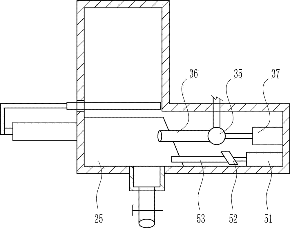
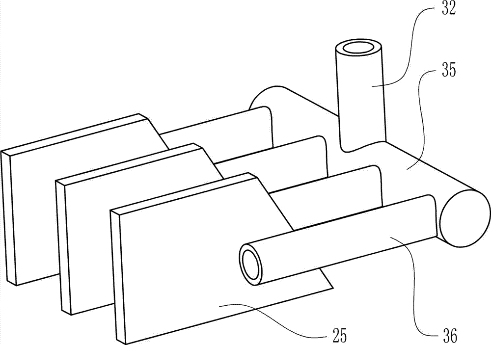
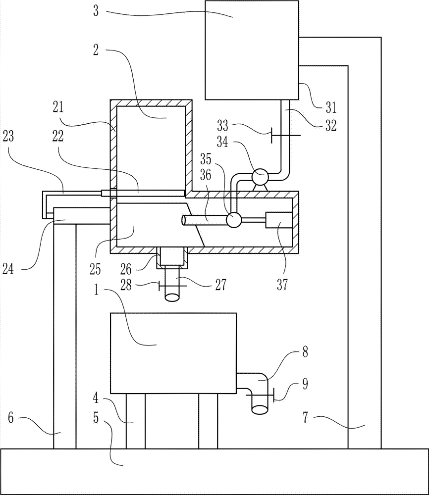
[0028] A vertical dissolving device for rare earth chloride, such as Figure 1-4 As shown, include dissolving tank 1, feeding device 2, water adding device 3, supporting legs 4, base 5, large support 6, L-shaped support 7, discharge liquid pipe 8 and discharge liquid valve 9; A feeding device 2 is arranged above the feeding device 2, and a water adding device 3 is arranged above the feeding device 2. Several legs 4 are welded on the bottom of the dissolving tank 1, and the lower ends of the legs 4 are connected to the top of the base 5 by welding. The large bracket 6 is arranged on the left side of the dissolving cylinder 1, the lower end of the large bracket 6 is connected to the top of the base 5 by welding, the L-shaped bracket 7 is arranged on the right side of the dissolving cylinder 1, the lower end of the L-shaped bracket 7 is connected to the top of the base 5 Connected by welding, the lower part of the right side wall of the dissolving cylinder 1 is connected with the...

Embodiment 2

[0030] A vertical dissolving device for rare earth chloride, such as Figure 1-4 As shown, include dissolving tank 1, feeding device 2, water adding device 3, supporting legs 4, base 5, large support 6, L-shaped support 7, discharge liquid pipe 8 and discharge liquid valve 9; A feeding device 2 is arranged above the feeding device 2, and a water adding device 3 is arranged above the feeding device 2. Several legs 4 are welded on the bottom of the dissolving tank 1, and the lower ends of the legs 4 are connected to the top of the base 5 by welding. The large bracket 6 is arranged on the left side of the dissolving cylinder 1, the lower end of the large bracket 6 is connected to the top of the base 5 by welding, the L-shaped bracket 7 is arranged on the right side of the dissolving cylinder 1, the lower end of the L-shaped bracket 7 is connected to the top of the base 5 Connected by welding, the lower part of the right side wall of the dissolving cylinder 1 is connected with the...

Embodiment 3

[0033] A vertical dissolving device for rare earth chloride, such as Figure 1-4 As shown, include dissolving tank 1, feeding device 2, water adding device 3, supporting legs 4, base 5, large support 6, L-shaped support 7, discharge liquid pipe 8 and discharge liquid valve 9; A feeding device 2 is arranged above the feeding device 2, and a water adding device 3 is arranged above the feeding device 2. Several legs 4 are welded on the bottom of the dissolving tank 1, and the lower ends of the legs 4 are connected to the top of the base 5 by welding. The large bracket 6 is arranged on the left side of the dissolving cylinder 1, the lower end of the large bracket 6 is connected to the top of the base 5 by welding, the L-shaped bracket 7 is arranged on the right side of the dissolving cylinder 1, the lower end of the L-shaped bracket 7 is connected to the top of the base 5 Connected by welding, the lower part of the right side wall of the dissolving cylinder 1 is connected with the...


PUM


Abstract

The invention relates to a dissolving device, in particular to a vertical type dissolving device for rare earth chloride. To solve the technical problem, the vertical type dissolving device for rare earth chloride is provided and comprises a dissolving vat, a feeding device, a water adding device, supporting legs, a base, a large support, an L-shaped support and the like, wherein the water adding device is arranged above the feeding device; a plurality of the supporting legs are welded at the bottom of the dissolving vat, and the lower ends of the supporting legs are connected with the top of the base in a welding manner; the large support is arranged on the left side of the dissolving vat, and the lower end of the large support is connected with the top of the base in a welding manner. According to the vertical type dissolving device for rear earth chloride, with adoption of the three-dimensional combination manner of the water adding device, the feeding device and the dissolving vat, occupied space is reduced, and the space utilization rate is increased.

Description

technical field [0001] The invention relates to a dissolving device, in particular to a vertical dissolving device for rare earth chloride. Background technique [0002] Rare earth elements have been discovered since the end of the 18th century. At that time, people often called the solid oxides insoluble in water as soil. Rare earths are generally separated in the form of oxides. Although the reserves on the earth are very large, it is difficult to smelt and purify them, so they are relatively rare, so they are named rare earths. Generally speaking, rare earths on earth exist in the form of rare earth oxides. Nowadays, rare earth has become an extremely important strategic resource. Rare earth element oxides refer to oxides of 15 lanthanide elements with atomic numbers from 57 to 71 in the periodic table of elements, and oxides of scandium and yttrium, a total of 17 elements whose chemical properties are similar to lanthanide elements. Rare earth elements have been widel...

Claims


Application Information

Patent Timeline
IPC IPC(8): B01F1/00B01F13/10B01F15/02
CPCB01F21/02B01F21/10B01F33/8212B01F35/712B01F35/7179
Inventor 李嘉驹刘淑钰彭嘉豪
Owner 阜阳佰恩得新材料技术有限公司
Why Eureka
Try Eureka