
Bar processing machine tool

A bar processing and machine tool technology, applied in the field of bar processing machine tools, can solve the problems of poor adjustability of the material rack, increase production cost, long waiting time, etc. Effect

Inactive Publication Date: 2017-12-15
江门市亿通精密科技有限公司
View PDF0 Cites 0 Cited by
  • Summary
  • Abstract
  • Description
  • Claims
  • Application Information

AI Technical Summary

Problems solved by technology

Due to the advantages of powder metallurgy technology, it has become the key to solve the problem of new materials and plays a pivotal role in the development of new materials. The process flow of powder metallurgy molding includes: mixing, pressing, sintering, machining, heat treatment, light Decoration, oil immersion, surface beating, shaping, sorting, oil flushing, press-fitting, etc., based on the consideration of labor costs and other factors, the production line is becoming more and more automated, intensive, and intelligent, and the various equipment in the production process are organically combined and connected. As a whole, the production efficiency is greatly improved and the production cost is reduced. Among them, the bar needs to be machined, the shell core parts and other parts are machined, and then the shell core parts are reinstalled into the shell processing parts, while the existing technology In the bar machining, after one bar is processed, another bar is re-clamped to the same material tube and material rack. On the other hand, the adjustability of the material rack is poor, and it takes a lot of waiting time Long, low efficiency, increased production costs

Method used


Image

  • Bar processing machine tool
  • Bar processing machine tool
  • Bar processing machine tool

Examples


Embodiment Construction

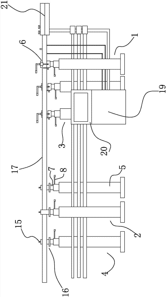
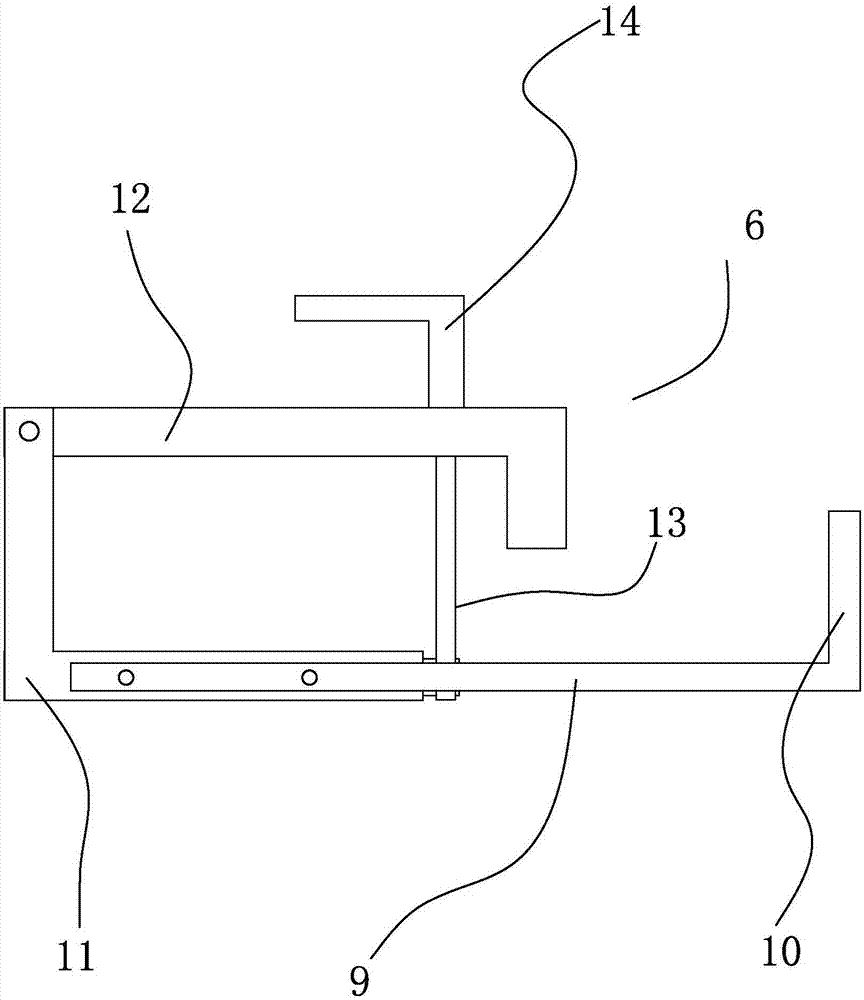
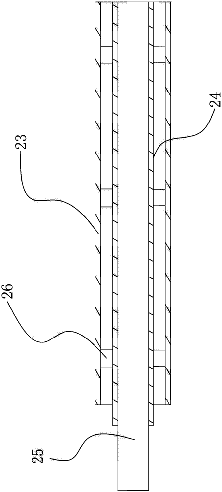
[0016] refer to Figure 1~4 , a bar processing machine tool, comprising a material tube 17, a pre-processing support 1, a post-processing support 2, a loading and unloading front support 3, and a loading and unloading rear support 4, and the material tube 17 is arranged on the processing front support 1, the post-processing support 2, On the front support 3 for loading and unloading and the support 4 after loading and unloading, there are two front support 3 for loading and unloading and two support 4 for rear loading and unloading respectively. , the pre-processing support 1 and the post-processing support 2 support and clamp the material tube 17, process the bar material discharged from the material tube 17, and on the other hand, install another material tube 17 with the bar material Clamped to one of the front brackets 3 for loading and unloading and the bracket 4 for loading and unloading, the front bracket 3 for loading and unloading and the rear bracket 4 for loading an...


PUM


Abstract

The invention relates to the field of machining equipment, and discloses a bar material processing machine tool. Two material pipes are respectively clamped through a pre-processing bracket, a post-processing bracket, a front loading and unloading bracket, and a rear loading and unloading bracket. The front loading and unloading bracket and the After loading and unloading, the bracket also acts as a transfer for the material tube. When one material tube is used for processing, the other material tube can be used for feeding. Enhanced performance, short waiting time, high efficiency, and reduced production costs.

Description

technical field [0001] The invention relates to the field of machining equipment, in particular to a bar processing machine tool. Background technique [0002] Powder metallurgy is a process technology for producing metal powder or using metal powder (or a mixture of metal powder and non-metal powder) as raw material, forming and sintering to manufacture metal materials, composite materials and various types of products. The powder metallurgy method has similarities with the production of ceramics, and both belong to the powder sintering technology. Therefore, a series of new powder metallurgy technologies can also be used for the preparation of ceramic materials. Due to the advantages of powder metallurgy technology, it has become the key to solve the problem of new materials and plays a pivotal role in the development of new materials. The process flow of powder metallurgy molding includes: mixing, pressing, sintering, machining, heat treatment, light Decoration, oil imme...

Claims


Application Information

Patent Timeline
IPC IPC(8): B22F3/24
CPCB22F3/24B22F2003/247
Inventor 张裕权
Owner 江门市亿通精密科技有限公司
Features
  • Generate Ideas
  • Intellectual Property
  • Life Sciences
  • Materials
  • Tech Scout
  • Unparalleled Data Quality
  • Higher Quality Content
  • 60% Fewer Hallucinations
Learn More