O-shaped shaft clasping type large-current seam welding electrode

A high-current, shaft-type technology, applied in the direction of electrode characteristics, roller electrode welding, etc., can solve the problems of short service life of the electrode, damage of the roller electrode, and influence on the stability of the transmission current, so as to prevent the oxidation of the silver tile surface and prolong the service life. life, and the effect of reducing the receiving area

Inactive Publication Date: 2017-12-15
成都焊研科盛焊接设备有限公司
View PDF0 Cites 4 Cited by
  • Summary
  • Abstract
  • Description
  • Claims
  • Application Information

AI Technical Summary

Problems solved by technology

When it is affected by factors such as vibration in the transmission process, because the conductive block is in an unstable state of floating, the reliability of contact with the conductive surface is poor, and large currents cannot be effectively transmitted, which reduces the load capacity of the roller electrode and directly affects the transmission. The stability of the current, and the phenomenon of ignition due to poor contact of the conductive surface will also cause damage to the roller electrode; the soft copper sheet vibrates frequently, and under the action of its own tension, when working for a long time, the soft copper sheet and the conductive base 1. The connection of the conductive block is prone to loosening, which increases the conductive resistance of the connection and burns out; the conductive silver sheet between the rotating spindle and the conductive block is easy to oxidize, there is no lubrication between them, the wear resistance is poor, and the service life of the electrode is short

Method used


Image

  • O-shaped shaft clasping type large-current seam welding electrode
  • O-shaped shaft clasping type large-current seam welding electrode
  • O-shaped shaft clasping type large-current seam welding electrode

Examples


Embodiment Construction

[0026] The present invention will be further described below with reference to the accompanying drawings and examples, and the implementation of the present invention includes but not limited to the following examples.

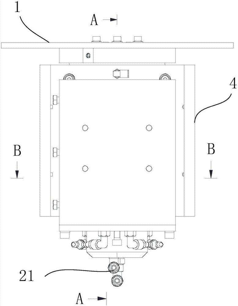
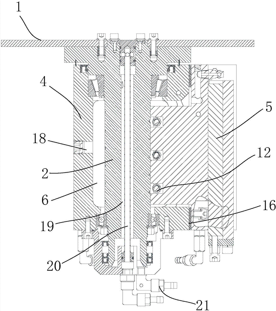
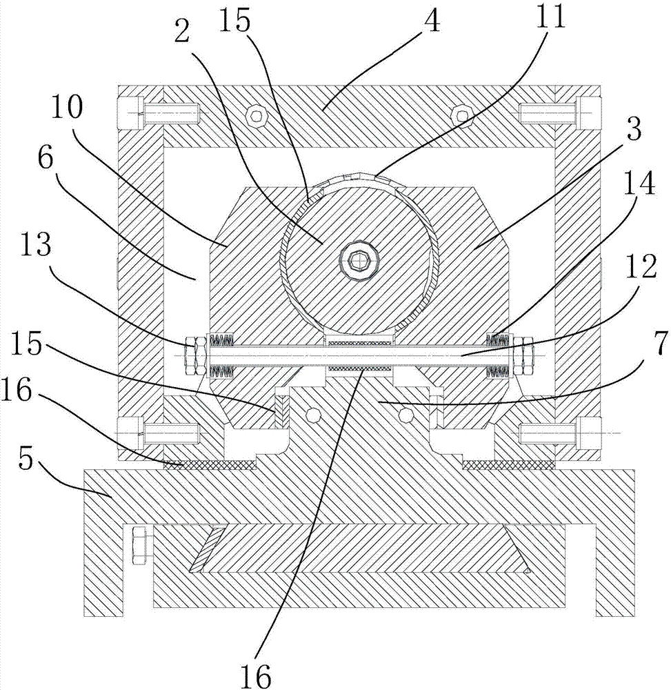
[0027] Such as Figure 1~5 As shown, an O-shaped shaft-holding high-current seam welding electrode includes an electrode roller 1, a rotating spindle 2, a conductive block 3, a shell 4, and a conductive base 5; wherein, the conductive block 3 is an O-shaped embracing, conductive The block 3 includes two conductive base blocks 10 arranged symmetrically along the main axis of rotation 2, used to fasten the two conductive base blocks 10 so that the conductive block 3 is close to the fastening bolt assembly of the main shaft of rotation 2, and arranged on the upper part of the conductive base block 10 The connecting wire 11 used to connect two conductive base blocks 10, the conductive base 10 is provided with an arc-shaped groove that fits with the rotating main s...


PUM


Abstract

The invention discloses an O-shaped shaft-embracing high-current seam welding electrode, which includes an electrode roller, a rotating main shaft that is fixedly connected with the electrode rolling disc and used to drive the rotation of the electrode rolling disc, and an O-shaped embracing type that surrounds and clings to the rotating main shaft. Conductive block, a shell arranged outside the conductive block, a conductive base arranged at the lower part of the conductive block; a cavity is provided between the shell and the conductive block and the conductive block is not in contact with the shell, and the upper part of the conductive base is provided with a convex The boss is provided with a bump, the bump is provided with a groove, and the conductive block includes two conductive base blocks symmetrically arranged along the main axis of rotation, which are used to fasten the two conductive base blocks to make the conductive block close to the fastening bolt assembly of the rotating spindle, the fastening bolt assembly includes a fastening bolt passing through two conductive base blocks and fastening nuts arranged at both ends of the fastening bolt, the fastening nut and the conductive base block A pre-tightening spring is arranged between them, and the lower part of the conductive base block is attached to the side of the boss.

Description

technical field [0001] The invention relates to the field of seam welding electrodes, in particular to an O-shaped shaft-holding high-current seam welding electrode. Background technique [0002] The conduction of the seam welding machine electrode roller is to transmit current through the sliding contact between the rotating main shaft and the static conductive block. In the traditional structure, the conductive block and the rotating main shaft should not only maintain sliding contact, but also need to maintain contact with the conductive transition block. Static contact, or a soft connection with a soft copper sheet and a fixed conductive base, so that the current of the conductive base can be transferred to the rotating roller. When it is affected by factors such as vibration in the transmission process, because the conductive block is in an unstable state of floating, the reliability of contact with the conductive surface is poor, and large currents cannot be effectivel...

Claims


Application Information

Patent Timeline
Patent Type & Authority Applications(China)
IPC IPC(8): B23K11/06B23K11/30
CPCB23K11/06B23K11/30
Inventor 费腾邵宁黄文权
Owner 成都焊研科盛焊接设备有限公司
Why Eureka
Try Eureka