Multi-head machining center and tool changing method using multi-head machining center

A machining center and multi-head technology, applied in metal processing equipment, metal processing machinery parts, manufacturing tools, etc., can solve the problems of long tool change time, low tool change efficiency, pollution, etc., to optimize the overall layout and improve tool change efficiency , The effect of increasing the capacity of the tool magazine

Inactive Publication Date: 2017-12-15
SUZHOU GFD AUTOMATION TECH
View PDF5 Cites 11 Cited by
  • Summary
  • Abstract
  • Description
  • Claims
  • Application Information

AI Technical Summary

Problems solved by technology

[0007] First, the tool capacity of the in-line tool magazine is limited;
[0008] Second, when changing the tool, the tool magazine is first pushed out, and then the processing machine head puts the original tool back into the tool magazine, and then takes out the tool. The tool changing time is relatively long and the tool changing efficiency is low;
[0009] Third, the tool is exposed on the tool holder and is easily polluted by the external environment, which affects the assembly accuracy of the processing head

Method used


Image

  • Multi-head machining center and tool changing method using multi-head machining center
  • Multi-head machining center and tool changing method using multi-head machining center
  • Multi-head machining center and tool changing method using multi-head machining center

Examples


Embodiment Construction

[0062] In order to more clearly illustrate the above-mentioned purpose, features and advantages of the present invention, specific implementations of the present invention will be described in detail in this part with reference to the accompanying drawings. In addition to the various implementations described in this section, the present invention can also be implemented in other different ways, without departing from the spirit of the present invention, those skilled in the art can make corresponding improvements, deformations and replacements, so the present invention Do not be bound by the specific embodiments disclosed in this section. The protection scope of the present invention should be determined by the claims.

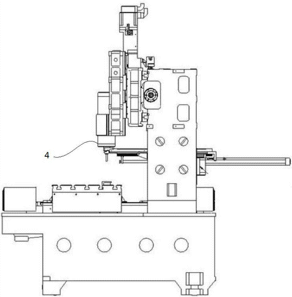
[0063] The purpose of the present invention is not only to solve the following technical problems, the cutter capacity of the in-line tool magazine is limited, and when the tool is changed, the tool magazine is first pushed out, and then the processing head p...


PUM


Abstract

The invention discloses a multi-head machining center and a tool changing method using the multi-head machining center. The multi-head machining center comprises at least two machining machine heads, at least two tool magazines, a tool driving mechanism, at least two tool arms and a tool arm driving mechanism, wherein each tool magazine is used for changing tools with one corresponding machining machine head, and is provided with multiple tools; all the tools are mounted on the tool magazines in the peripheral direction; the tool driving mechanism is used for driving each tool to move to a tool changing fixed point in the peripheral direction; two ends of the tool arms can respectively hold the tools to be changed of the machining machine heads and preset tools of the tool magazines; and the tool arm driving mechanism is used for driving the tool arms to rotate to enable two ends of each tool arm to respectively take the preset tools and the tools to be changed from the tool magazines and the machining machine heads and respectively charging the preset tools and the tools to be changed in the tool magazines and the machining machine heads. The multi-head machining center realizes the tool arrangement of multiple tool magazines cooperating with multiple tools, improves the capacity of the tool magazines, optimizes overall layout thereof, reduces the size thereof, and improves the tool changing efficiency.

Description

technical field [0001] The invention relates to the field of machining, in particular to a multi-head machining center and a tool changing method using the multi-head machining center. Background technique [0002] Machine tools are often used in the 3C industry, especially the mobile phone parts processing industry, in order to process fine parts, such as turning and milling parts. At present, the mainstream processing machine tools are still single-head machining centers, and multi-head machining centers are not commonly used. [0003] Whether it is a single-head machining center or a multi-head machining center, it generally includes a tool magazine and a tool change mechanism. The tool magazine is used for positioning and installing tools. One tool magazine can accommodate multiple tools. The capacity of the tool magazine is directly related to the number of tools that are positioned and installed on it. The tool change mechanism is used to exchange the tool between th...

Claims


Application Information

Patent Timeline
Patent Type & Authority Applications(China)
IPC IPC(8): B23Q3/155
CPCB23Q3/155B23Q3/15506
Inventor 毛文亮吴勇勇郭颖俊
Owner SUZHOU GFD AUTOMATION TECH
Why Eureka
Try Eureka