Cleaning device for insulating paint for auxiliary transformer iron core

A technology of auxiliary transformer and cleaning device, which is applied to grinding/polishing safety devices, grinding machines, grinding/polishing equipment, etc., can solve the problems of waste of resources, low practicality of cleaning equipment, and difficulty in cleaning insulating paint collection, etc. collection effect

Inactive Publication Date: 2017-12-15
胡宇妠
View PDF10 Cites 4 Cited by
  • Summary
  • Abstract
  • Description
  • Claims
  • Application Information

AI Technical Summary

Problems solved by technology

[0006] In order to overcome the disadvantages in the prior art that the insulating varnish can only be removed for chips with the same thickness, the practicability of the removal equipment is low, and it is difficult to collect the insulating varnish, which causes waste of resources, the technology to be solved by the present invention The problem is to provide a device for removing insulating varnish from chips with different thicknesses, which can improve the practicability of the removal equipment and facilitate the collection of the removed insulating varnish without causing waste of resources.

Method used


Image

  • Cleaning device for insulating paint for auxiliary transformer iron core
  • Cleaning device for insulating paint for auxiliary transformer iron core
  • Cleaning device for insulating paint for auxiliary transformer iron core

Examples


Embodiment 1

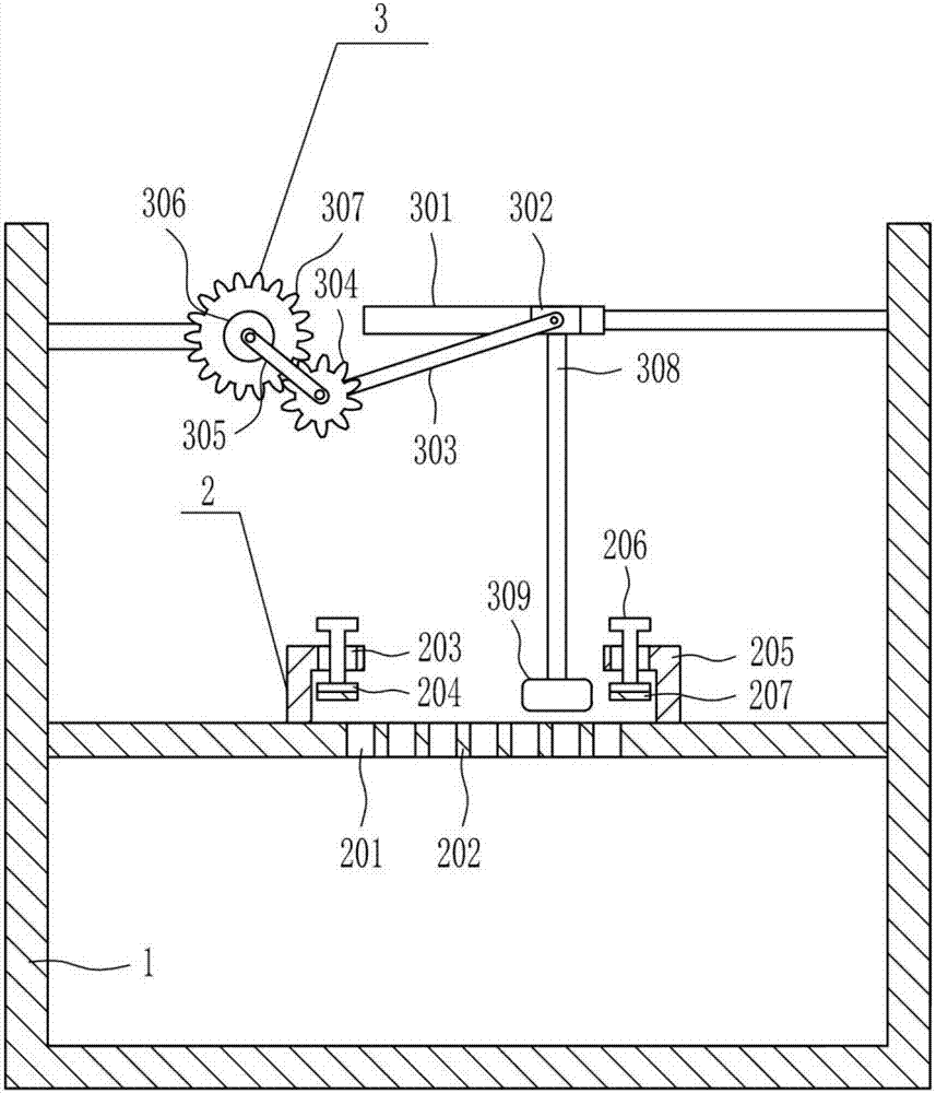
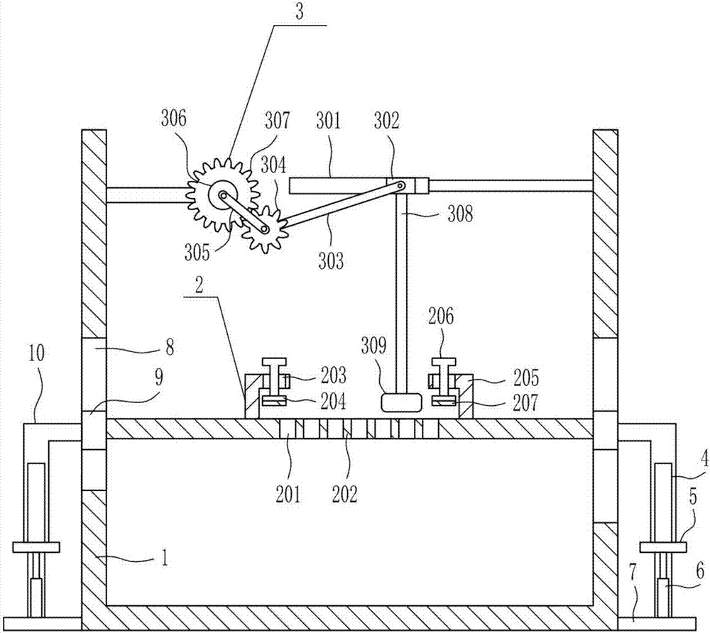
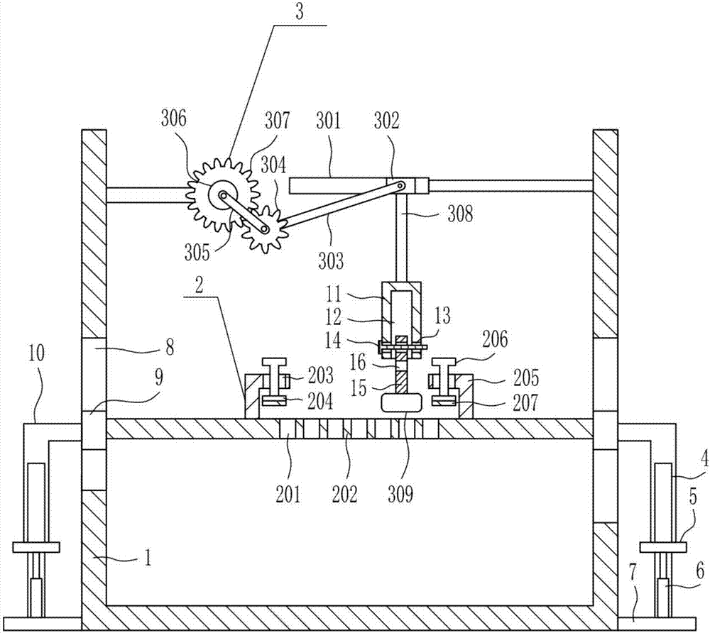
[0032] A device for removing insulating varnish for auxiliary transformer iron core, such as Figure 1-5 As shown, it includes a frame 1, a fixing mechanism 2 and a clearing mechanism 3, the upper part of the top of the frame 1 is connected with a clearing mechanism 3, and the middle part of the frame 1 is connected with a fixing mechanism 2.

Embodiment 2

[0034] A device for removing insulating varnish for auxiliary transformer iron core, such as Figure 1-5 As shown, it includes a frame 1, a fixing mechanism 2 and a clearing mechanism 3, the upper part of the top of the frame 1 is connected with a clearing mechanism 3, and the middle part of the frame 1 is connected with a fixing mechanism 2.

[0035] The fixing mechanism 2 includes a placing plate 202, a pressing block 204, a fixing rod 205, a bolt 206 and a first rubber pad 207. The middle part of the frame 1 is connected with the placing plate 202, and the middle part of the placing plate 202 is evenly opened with a first through hole 201. The top of the placement plate 202 is symmetrically connected with fixed rods 205. The fixed rods 205 are all provided with first threaded holes 203. The first threaded holes 203 are connected with bolts 206 by means of threaded connections. The bottom ends of the bolts 206 are connected with pressure The block 204 and the bottom of the p...

Embodiment 3

[0037] A device for removing insulating varnish for auxiliary transformer iron core, such as Figure 1-5 As shown, it includes a frame 1, a fixing mechanism 2 and a clearing mechanism 3, the upper part of the top of the frame 1 is connected with a clearing mechanism 3, and the middle part of the frame 1 is connected with a fixing mechanism 2.

[0038] The fixing mechanism 2 includes a placing plate 202, a pressing block 204, a fixing rod 205, a bolt 206 and a first rubber pad 207. The middle part of the frame 1 is connected with the placing plate 202, and the middle part of the placing plate 202 is evenly opened with a first through hole 201. The top of the placement plate 202 is symmetrically connected with fixed rods 205. The fixed rods 205 are all provided with first threaded holes 203. The first threaded holes 203 are connected with bolts 206 by means of threaded connections. The bottom ends of the bolts 206 are connected with pressure The block 204 and the bottom of the p...


PUM


Abstract

The invention relates to a cleaning device, in particular to a cleaning device for insulating paint for an auxiliary transformer iron core. The invention aims to solve the technical problem about providing the cleaning device for the insulating paint for the auxiliary transformer iron core, which can clean the insulating paint of chips with different thickness, can improve the practicability of cleaning equipment and can collect cleaned insulating paint without causing resource waste. In order to solve the technical problem, the invention provides the cleaning device for the insulating paint for the auxiliary transformer iron core, which comprises a machine frame and the like; the upper part of the top in the machine frame is connected with a cleaning mechanism; and the middle part in the machine frame is connected with a fixing mechanism. According to the cleaning device for the insulating paint for the auxiliary transformer iron core, the purpose of wearing and removing the insulating paint on a strip-shaped iron core is achieved by arranging the fixing mechanism and the cleaning mechanism; and the purpose of preventing blockage can be achieved by loosening and pulling a pulling rod discontinuously.

Description

technical field [0001] The invention relates to a cleaning device, in particular to a cleaning device for insulating varnish used in auxiliary transformer cores. Background technique [0002] The transformer is a device that uses the principle of electromagnetic induction to change the AC voltage. The main components are the primary coil, the secondary coil and the iron core (magnetic core). The main functions are: voltage transformation, current transformation, impedance transformation, isolation, voltage stabilization (magnetic saturation transformer), etc. According to the use, it can be divided into: power transformers and special transformers (electric furnace transformers, rectifier transformers, power frequency test transformers, voltage regulators, mining transformers, audio transformers, intermediate frequency transformers, high frequency transformers, impact transformers, instrument transformers, electronic transformers , reactors, transformers, etc.). [0003] I...

Claims


Application Information

Patent Timeline
Patent Type & Authority Applications(China)
IPC IPC(8): B24B27/033B24B41/02B24B55/12B24B55/00B24B41/06B24B27/00
CPCB24B27/033B24B27/0015B24B41/02B24B41/06B24B55/00B24B55/12
Inventor 胡宇妠向珂夏瑜
Owner 胡宇妠
Why Eureka
Try Eureka