
Plate connecting structure for prestressed concrete member tensioning mechanism

A tensioning mechanism and plate connection technology, applied in the plate field, can solve problems such as leakage of tensioning nut, damage to tensioning nut, damage to the end face of prestressed concrete members, etc., and achieve the effect of preventing damage and avoiding contact.

Inactive Publication Date: 2017-12-15
周兆弟
View PDF0 Cites 0 Cited by
  • Summary
  • Abstract
  • Description
  • Claims
  • Application Information

AI Technical Summary

Problems solved by technology

[0004] However, the prestressed concrete members formed in the traditional tensioning technology scheme often have tension nut leakage, which causes the tension nuts to contact each other when the prestressed concrete members are docked, resulting in damage to the tension nuts, and even damage to the prestressed concrete members. end face damage

Method used


Image

  • Plate connecting structure for prestressed concrete member tensioning mechanism
  • Plate connecting structure for prestressed concrete member tensioning mechanism
  • Plate connecting structure for prestressed concrete member tensioning mechanism

Examples


Embodiment 1

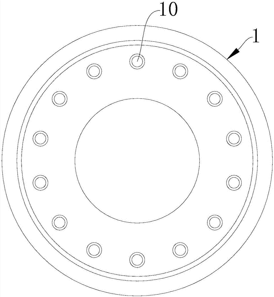
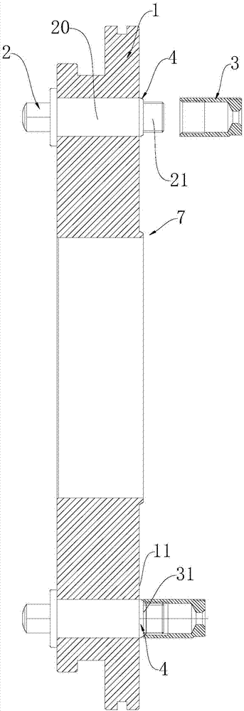
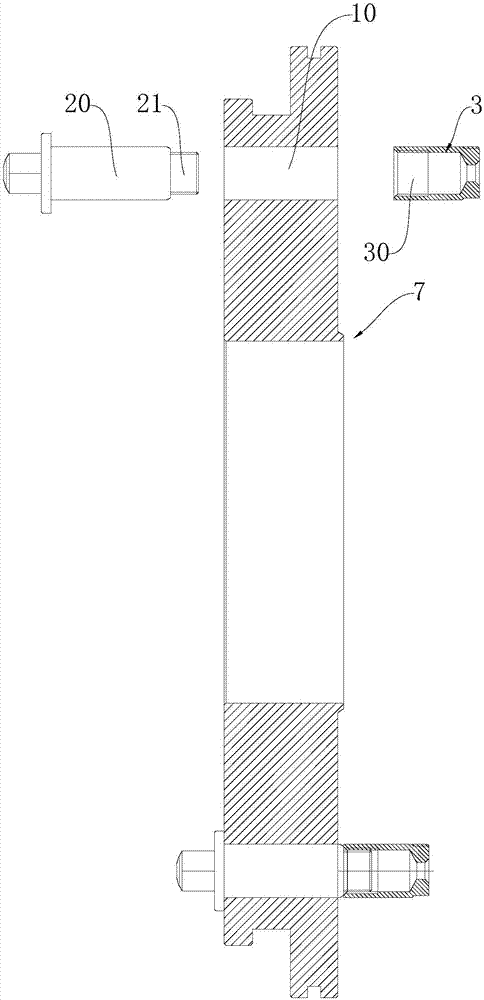
[0039] Such as Figure 2 to Figure 5 As shown, the abutting portion 4 is integrally formed with the connecting bolt 2 .

[0040] Specifically, such as figure 2 with image 3 As shown, the connecting bolt 2 includes an insertion part 20 and a connection part 21 located at the top of the insertion part 20 and is suitable for fixed connection with the tension nut 3; the outer diameter of the end surface of the connection part 21 is consistent with the inner cavity outer diameter of the tension nut 3 The outer diameter of the end surface of the inserting portion 20 is larger than that of the connecting portion 21 , and when the connecting bolt 2 is inserted into the through hole 10 , the inserting portion 20 partially protrudes from the end surface of the plate body 1 to form the contact portion 4 .

Embodiment 2

[0042] Such as Figure 4 with Figure 5 As shown, the outer diameter of the connecting bolt 2 is consistent with the outer diameter of the inner cavity of the tension nut 3, and the outer periphery of one end close to the tension nut 3 is provided with a protruding portion 40 extending radially outward, and the protruding portion 40 is consistent with the connecting bolt 2. The abutting portion 4 is integrally formed, and the opposite end is provided with a locking piece 5 suitable for locking the connecting bolt 2 .

Embodiment 3

[0044] Such as Image 6 with Figure 8As shown, the outer diameter of the connecting bolt 2 is consistent with the outer diameter of the inner cavity of the tension nut 3, which is inserted into the through hole 10, and the pad protruding from the end surface of the plate body 1 is sleeved and connected to the end surface 11 of the plate body 1. The sheet 6 and the washer 6 extend radially outward to form the contact portion 4 .

[0045] In addition, it should also be pointed out that in the above technical solution, the abutment portion 4 protrudes at least 1 mm from the end surface of the board body 1 .

[0046] In addition, a protruding protruding structure 7 is provided at the center of the plate body 1 , and the protruding structure 7 and the abutting portion 4 are located on the same side of the plate body 1 .

[0047] The function of the raised structure 3 is to increase the strength of the tension plate and the fixed plate. At the same time, during centrifugation, th...


PUM


Abstract

The invention provides a plate connection structure used in the tensioning mechanism of prestressed concrete members, which includes a plate body provided with a plurality of through holes, the through holes run through the plate body and are distributed at even intervals along the end surface of the plate body; The bolts are in one-to-one correspondence with several through holes, the connecting bolts are inserted into the through holes, and the outwardly extending part passes through the through holes, inserted into the corresponding tension nuts, and fixedly connected with the tension nuts; the tension nuts are opposite to the plate body An abutting portion connected with the connecting bolt and suitable for abutting against the end surfaces of the tension nuts is interposed between the end surfaces of the tension nuts. The technical scheme makes use of the protruding abutting portion formed in the connection structure to sink the tension nut into the prestressed concrete component without being exposed during the forming process of the prestressed concrete component.

Description

technical field [0001] The invention relates to a plate used in a tensioning mechanism of a prestressed concrete member. Background technique [0002] At present, prestressed concrete components, such as pipe piles, square piles, T-shaped piles, etc., are important pile foundation materials, which are widely used in the foundation engineering of various buildings and structures, such as high-rise buildings, public buildings, general industrial , Civil buildings, ports, docks, highways, bridges and other fields. When pouring piles with concrete, it needs to go through a very important process, that is, the tensioning process. [0003] During tensioning, the fixed plate is usually used to anchor one end of the tension module, and the other end is stretched and displaced by the tension plate. It will cause the tensile module to tilt, that is, the steel rod or steel strand to bend, resulting in unqualified or failed tension, and affecting the quality of the pipe pile. In addi...

Claims


Application Information

Patent Timeline
Patent Type & Authority Applications(China)
IPC IPC(8): B28B23/04
CPCB28B23/043
Inventor 周兆弟
Owner 周兆弟
Learn More