An oil drum handling device

A technology for handling devices and oil drums, applied in transportation and packaging, multi-axis trolleys, motor vehicles, etc., can solve the problems of high labor costs and unsafety in handling oil drums, and achieve fast and convenient clamping, safe handling, and avoid bumps damage effect

Active Publication Date: 2019-11-19
博白县计量和产品质量检测中心
View PDF4 Cites 0 Cited by
  • Summary
  • Abstract
  • Description
  • Claims
  • Application Information

AI Technical Summary

Problems solved by technology

[0003] The purpose of the present invention is to provide an oil drum handling device to solve the problems of high manpower cost and unsafety in handling oil drums.

Method used


Image

  • An oil drum handling device
  • An oil drum handling device
  • An oil drum handling device

Examples


Embodiment Construction

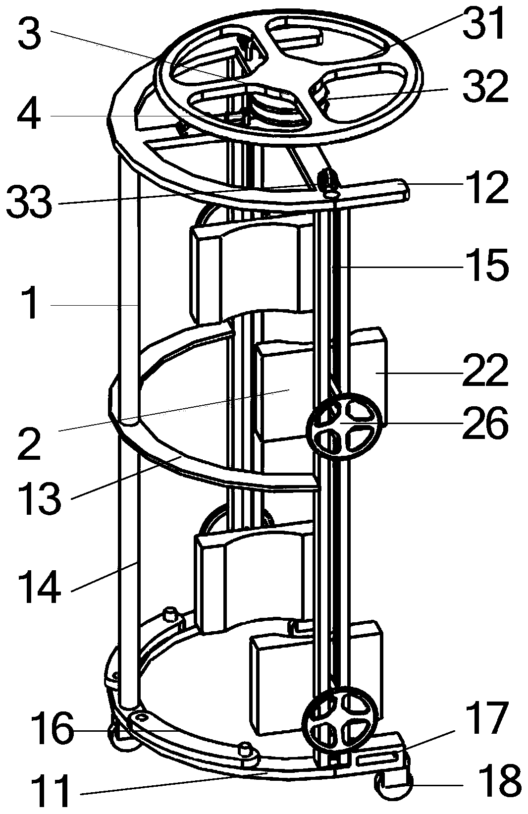
[0027] Such as figure 1 As shown, the oil drum handling device includes a frame 1 , a clamping part 2 , a lifting part 3 and a rotation limiting device 4 . The frame 1 is semi-cylindrical, and the clamping part 2 is arranged symmetrically on both sides of the frame 1. The clamping part 2 is divided into upper and lower groups. The upper end surface is used to control the one-way rotation of the lifting part 3 .

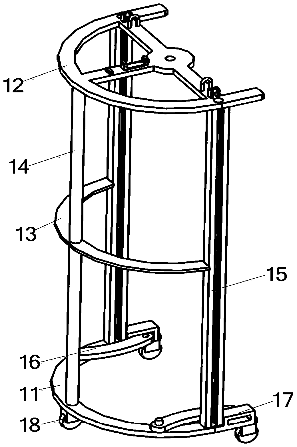
[0028] Such as figure 2 As shown, the frame 1 includes a semi-arc bottom plate 11 arranged at the bottom, a top plate 12 is arranged directly above the bottom plate 11, and three columns 14 are arranged between the bottom plate 11 and the top plate 12, and the three columns 14 are respectively located in the middle of the bottom plate 11 and two At the end, the columns 14 located at both ends of the bottom plate 11 are provided with guide rails 15 along the length direction of the columns, and the middle and both ends of the bottom surface of the bottom plate 11 ar...


PUM


Abstract

The invention provides an oil drum carrying device, and belongs to the field of oil drum carrying equipment. The oil drum carrying device comprises a frame, clamping parts and a pulling-up part. The frame comprises a semi-circular arc-shaped bottom plate arranged at the lower part. A top plate is arranged over the bottom plate. Stand columns and guiding columns are arranged between the bottom plate and the top plate. The stand columns are arranged in the middle of the bottom plate. The guiding columns are arranged at the two ends of the bottom plate. The guiding columns are correspondingly provided with guiding rails. Vehicle wheels with self-locking parts are arranged at the middle and the two ends of the lower end surface of the bottom plate. Each clamping part comprises a moving part arranged on the guiding rails. The moving parts are installed on the guiding rails through wheel sets and slide along the guiding rails. The pulling-up part comprises a second wheel disc, a fixed pulley, a limiting ring and a pulling-up rope. By means of the oil drum carrying device, the problems that the manual cost needed by carrying an oil drum is high, and carrying is not safe are solved.

Description

technical field [0001] The invention relates to the field of oil barrel handling equipment, in particular to an oil barrel handling device. Background technique [0002] In the manufacturing industry, it is often necessary to use a large amount of liquid auxiliary oil, such as drawing oil, lubricating oil, engine oil, etc. These auxiliary oils are generally stored in large iron drums or plastic drums, and these large oil drums are generally columnar structure, and the weight is relatively large, there is generally no handle on the oil drum, the workload of manual handling is large, and the handling efficiency is low; when the oil drum needs to be moved during the production process, usually multiple workers first lift the oil drum and put it on the handle On the truck, and then move the truck to the desired location, this method of transportation requires the cooperation of multiple people, and it is easy to cause bumps and other injuries to the workers during the process of...

Claims


Application Information

Patent Timeline
Patent Type & Authority Patents(China)
IPC IPC(8): B62B3/02B62B3/04
CPCB62B3/02B62B3/04
Inventor 覃永红
Owner 博白县计量和产品质量检测中心
Why Eureka
Try Eureka