
Cloth winding drum device for textile machinery

A cloth reel and textile machinery technology, applied in the direction of winding strips, thin material processing, transportation and packaging, etc., can solve the problems of inability to meet modern large-scale textile production, difficult installation and disassembly, cumbersome reel replacement, etc. Achieve the effects of simple structure, avoid slippage and improve production efficiency

Inactive Publication Date: 2017-12-15
湖州胎福工艺品有限公司
View PDF0 Cites 15 Cited by
  • Summary
  • Abstract
  • Description
  • Claims
  • Application Information

AI Technical Summary

Problems solved by technology

[0002] As we all know, after the weaving is completed, the cloth is rolled into rolls and divided into packages. The formation of each roll of cloth is usually formed by winding the cloth on it under the drive of the drive device. It is found during long-term use that the replacement of the roll It is very cumbersome and inconvenient to operate, difficult to install and disassemble, and because there is no clamping mechanism on the reel, it is necessary to manually wind the cloth on the reel for a few turns before automatic winding can be carried out. This method is time-consuming , laborious, so it cannot meet the needs of modern large-scale textile production, causing certain troubles to enterprises

Method used


Image

  • Cloth winding drum device for textile machinery
  • Cloth winding drum device for textile machinery
  • Cloth winding drum device for textile machinery

Examples


Embodiment Construction

[0019] The following will clearly and completely describe the technical solutions in the embodiments of the present invention with reference to the accompanying drawings in the embodiments of the present invention. Obviously, the described embodiments are only some, not all, embodiments of the present invention.

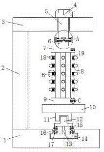
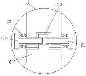
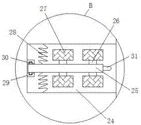
[0020] refer to Figure 1-4 , a cloth reel device for textile machinery, comprising a base 1, a support column 2 is fixedly connected to one side of the upper end of the base 1, and a top plate 3 is fixedly connected to the top of the support column 2, and a driving motor 4 is provided on the upper end of the top plate 3, And the lower end of drive motor 4 is provided with rotating shaft 5, and rotating shaft 5 passes the inner wall of top plate 3 outward extension and is provided with limit groove 20, and the first lug 6 is inserted in the limit groove 20, the first lug 6 The lower end is fixedly connected with a first fixed plate 7, and the bottom end of the first ...


PUM


Abstract

The invention discloses a cloth reel device for textile machinery, comprising a base, a support column is fixedly connected to one side of the upper end of the base, and a top plate is fixedly connected to the top end of the support column, and a driving motor is arranged on the upper end of the top plate. And the lower end of the driving motor is provided with a rotating shaft, and the outward extension end of the rotating shaft passing through the inner wall of the top plate is provided with a limiting groove, and a first protrusion is inserted in the limiting groove, and the lower end of the first protrusion is fixedly connected with a The first fixed plate, the bottom end of the first fixed plate is evenly surrounded by several reels, the lower end of the second fixed plate is fixedly connected with the first fixed block through the disc, the lower end of the first fixed block A second protruding block is inserted through the groove, and the second protruding block is fixedly connected with a circular clamping block through the telescopic rod. The invention has the advantages of simple structure, easy installation and disassembly, more convenient cloth coiling, no manual winding, reduced labor force, improved production efficiency, and is suitable for wide popularization.

Description

technical field [0001] The invention relates to the technical field of textile machinery, in particular to a cloth reel device for textile machinery. Background technique [0002] As we all know, after the weaving is completed, the cloth is rolled into rolls and divided into packages. The formation of each roll of cloth is usually formed by winding the cloth on it under the drive of the drive device. It is found during long-term use that the replacement of the roll It is very cumbersome and inconvenient to operate, difficult to install and disassemble, and because there is no clamping mechanism on the reel, it is necessary to manually wind the cloth on the reel for a few turns before automatic winding can be carried out. This method is time-consuming , laborious, so can not meet the needs of modern large-scale textile production, causing certain troubles to enterprises. Contents of the invention [0003] In order to solve the problems mentioned above in the background tec...

Claims


Application Information

Patent Timeline
Patent Type & Authority Applications(China)
IPC IPC(8): B65H18/04B65H18/26
CPCB65H18/04B65H18/26
Inventor 陈王骅
Owner 湖州胎福工艺品有限公司
Learn More