Road surface obstacle removing device for earthquake disaster

A barrier-removing device and disaster technology, which is applied in road cleaning, cleaning methods, construction, etc., can solve the problems of unclean cleaning, slow cleaning speed, and long time consumption.

Active Publication Date: 2017-12-15
融创达科技成果转化(江苏)有限公司
View PDF6 Cites 11 Cited by
  • Summary
  • Abstract
  • Description
  • Claims
  • Application Information

AI Technical Summary

Problems solved by technology

[0005] In order to overcome the shortcomings of slow cleaning speed, unclean cleaning, and long time-consuming in manual cleaning of the road surface, the technical problem to be solved by the present invention is to provide a road surface that can be quickly cleared, cleaned, and takes a short time, and at the same time can Road surface obstacle removal device for earthquake disasters to ensure the safety of the clearers themselves

Method used


Image

  • Road surface obstacle removing device for earthquake disaster
  • Road surface obstacle removing device for earthquake disaster
  • Road surface obstacle removing device for earthquake disaster

Examples


Embodiment 1

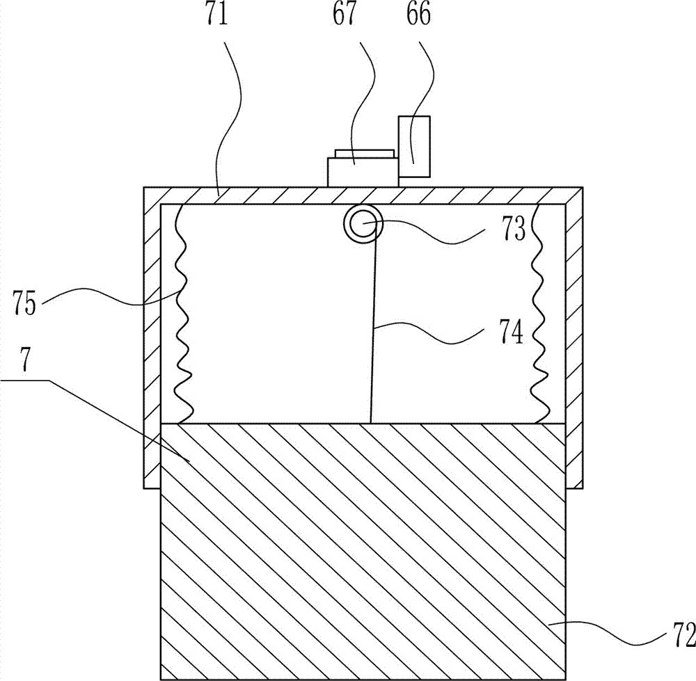
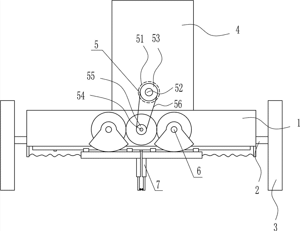
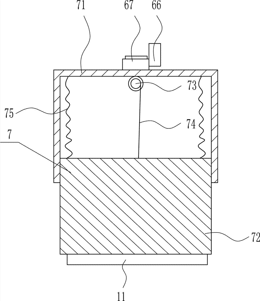
[0037] A road surface obstacle removal device for earthquake disasters, such as Figure 1-7 As shown, it includes a frame 1, a connecting rod 2, a wheel 3, a fixed plate 4, a driving device 5, a transmission device 6 and an obstacle removal device 7. The left and right sides of the frame 1 are provided with a connecting rod 2, and the connecting rod 2 is provided with Wheel 3, the top of frame 1 is vertically connected with fixed plate 4, and driving device 5 is installed on fixed plate 4, and the front side middle part of frame 1 is equipped with transmission device 6, and the bottom of frame 1 is equipped with obstacle removal device 7.

Embodiment 2

[0039] A road surface obstacle removal device for earthquake disasters, such as Figure 1-7 As shown, it includes a frame 1, a connecting rod 2, a wheel 3, a fixed plate 4, a driving device 5, a transmission device 6 and an obstacle removal device 7. The left and right sides of the frame 1 are provided with a connecting rod 2, and the connecting rod 2 is provided with Wheel 3, the top of frame 1 is vertically connected with fixed plate 4, and driving device 5 is installed on fixed plate 4, and the front side middle part of frame 1 is equipped with transmission device 6, and the bottom of frame 1 is equipped with obstacle removal device 7.

[0040] Drive unit 5 comprises first motor 51, first transmission shaft 52, large pulley 53, second transmission shaft 54, small pulley 55 and flat belt 56, and the middle part of fixed plate 4 front sides is equipped with first motor 51, the first motor The output shaft of 51 is connected with the first transmission shaft 52, the first tran...

Embodiment 3

[0042] A road surface obstacle removal device for earthquake disasters, such as Figure 1-7 As shown, it includes a frame 1, a connecting rod 2, a wheel 3, a fixed plate 4, a driving device 5, a transmission device 6 and an obstacle removal device 7. The left and right sides of the frame 1 are provided with a connecting rod 2, and the connecting rod 2 is provided with Wheel 3, the top of frame 1 is vertically connected with fixed plate 4, and driving device 5 is installed on fixed plate 4, and the front side middle part of frame 1 is equipped with transmission device 6, and the bottom of frame 1 is equipped with obstacle removal device 7.

[0043] Drive unit 5 comprises first motor 51, first transmission shaft 52, large pulley 53, second transmission shaft 54, small pulley 55 and flat belt 56, and the middle part of fixed plate 4 front sides is equipped with first motor 51, the first motor The output shaft of 51 is connected with the first transmission shaft 52, the first tran...


PUM


Abstract

The invention relates to unchoking equipment for an earthquake, in particular to a road surface obstacle removing device for an earthquake disaster. According to the unchoking equipment for the earthquake, obstacles can be rapidly removed, complete clearing is achieved, the consumed time is short, and meanwhile personal safety of a removing worker can be ensured. The unchoking equipment for the earthquake comprises a frame and the like, the left side and the right side of the frame are provided with connecting rods correspondingly, wheels are arranged on the connecting rods, and top of the frame is vertically connected with a fixing plate. A driving device is mounted on the fixing plate, a transmission device is mounted in the middle of the front side of the frame, and the bottom of the frame is provided with an obstacle removing device body. According to the unchoking equipment for the earthquake, through mutual cooperation of the driving device, the transmission device and the obstacle removing device body, the damaged road surface can be effectively cleared, and the effect that the obstacles can be rapidly removed, clearing is complete, the consumed time is short, and meanwhile the personal safety of the removing worker can be ensured are achieved.

Description

technical field [0001] The invention relates to dredging equipment for earthquakes, in particular to a road surface obstacle clearing device for earthquake disasters. Background technique [0002] Geological hazards, a professional term in geology, refer to geological processes (phenomena) that are formed under the action of natural or human factors and cause damage and loss to human life, property and the environment. Such as collapse, landslide, debris flow, ground fissure, soil erosion, land desertification and swamp, soil salinization, and earthquake, volcano, geothermal damage, etc. [0003] In the rescue process after geological disasters, there are still some gravel residues after large-scale mechanical equipment clears the road, and these are usually cleaned manually. Manual cleaning of the road surface has slow cleaning speed, unclean cleaning, It takes a long time, and at the same time, there may be a certain personal danger to the clearer itself. Therefore, there...

Claims


Application Information

Patent Timeline
Patent Type & Authority Applications(China)
IPC IPC(8): E01H1/00
Inventor 董芳婷周静郭玲娟段晶晶
Owner 融创达科技成果转化(江苏)有限公司
Why Eureka
Try Eureka