A kind of nesting method of inner and outer container of LNG storage tank

A technology of inner container and outer container, which is applied in the field of fitting the inner container into the outer container of liquefied natural gas cryogenic storage tanks, and can solve the problems of fitting and support setting difficulty

Active Publication Date: 2019-04-12
XINXING ENERGY EQUIP
View PDF5 Cites 2 Cited by
  • Summary
  • Abstract
  • Description
  • Claims
  • Application Information

AI Technical Summary

Problems solved by technology

[0004] In the above-mentioned nesting production process, the welding of the two heads of the outer container and the eight outer supports is single-sided welding, which does not meet the requirements of the classification society for the outer container of a marine LNG storage tank without manholes. The last circular joint between the cylinder and the head is allowed to adopt a welded joint with a lining ring, and the rest of the welds require full penetration welding.
For this reason, an outer container head needs to be welded on both sides first, and the number of support openings should be reduced as much as possible, which brings difficulties to fitting and support settings

Method used


Image

  • A kind of nesting method of inner and outer container of LNG storage tank
  • A kind of nesting method of inner and outer container of LNG storage tank
  • A kind of nesting method of inner and outer container of LNG storage tank

Examples


Embodiment Construction

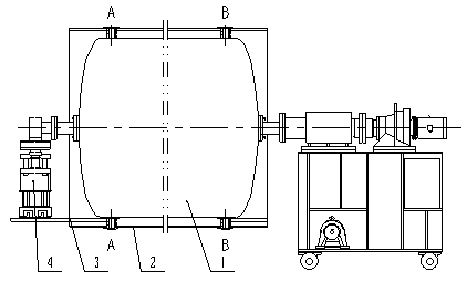
[0024] In this embodiment, one end of the outer container is welded. The upper four support structures of the A-A support section and the B-B support section are opened on the outer container, and the lower four support structures are not opened on the outer container. The fitting method is as follows, see the attachment for details Figure 2-9 .

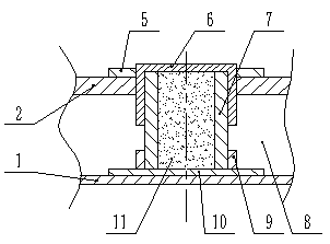
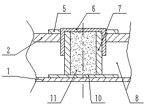
[0025] 1. Preparation of the outer container: as attached Figure 6 As shown, the head 12 and the outer cylinder 13 are welded together by double-sided welding, and the two support sections of the eight support structures are the A-A support section close to the head 12 and the B-B support section close to the fitting entrance of the outer container, wherein The support structure of the A-A support section is a sliding support, image 3 It is a schematic diagram of the upper sliding support structure of the A-A support section, and the two support points on the upper part of the outer container are opened; Figure 5 It is a schema...


PUM


Abstract

The invention discloses a sleeving method of inner and outer containers of an LNG (Liquefied Natural Gas) storage tank. The sleeving method comprises the steps of (1) preparing an outer container; (2) preparing an inner container; (3) preparing for sleeving; and (4) sleeving. Holes are formed in upper support points of the A-A and B-B support sections of the outer container, backing plates II are welded on lower support points of the A-A and B-B support sections of the outer container, an outer support ring is welded on a lower support point of the A-A section, and a glass fiber reinforced plastic support is inserted. Backing plates and an inner support ring are welded on support points of the inner container. The inner container is fixedly connected with a counterweight container, a connecting steel pipe is lifted, and the inner container is moved to sleeve. When the B-B section of the inner container reaches an inlet, the outer support ring sleeves the outer surface of the glass fiber reinforced plastic support filled with heat insulating materials, the glass fiber reinforced plastic support is pressed into the lower inner support ring, and the outer support ring and the glass fiber reinforced plastic support are supported to sleeve together with the inner container. In a specified position, the inner container falls so as to compress the glass fiber reinforced plastic support. The outer support ring of the B-B section is welded on the backing plate II, and then the upper support structure is welded, so that sleeving is completed. According to the sleeving method, the full penetration rate of the outer container is increased, leakage points of the outer container are reduced, and the vacuum leakage rate of an interlayer between the inner and outer containers is reduced.

Description

technical field [0001] The invention belongs to the application field of liquefied natural gas (LNG), and in particular relates to a method for fitting an inner container of a liquefied natural gas cryogenic storage tank into an outer container. Background technique [0002] As a kind of clean energy, natural gas is not only pollution-free after burning, but also has low cost. It has attracted more and more attention from the society, and its application fields have gradually expanded. Liquefied natural gas (LNG) is mostly stored and transported in twin-barrel low-temperature storage tanks. [0003] The LNG double-barreled low-temperature storage tank is an outer container fitted with an inner container, and a vacuum insulation interlayer structure is used between the inner and outer containers. In the production process, under normal circumstances, the inner container is inserted into the outer container, and then the heads at both ends of the outer container are welded. ...

Claims


Application Information

Patent Timeline
Patent Type & Authority Patents(China)
IPC IPC(8): F17C3/08
CPCF17C3/085F17C2209/221
Inventor 赵翠钗牛学忠武常生张相相崔闻天
Owner XINXING ENERGY EQUIP
Why Eureka
Try Eureka