
Eureka
For R&D, Eureka makes reading and utilizing patents & technical documents easy.
Eureka AIR
Designed for self-driven R&D workflows. Generate viable solutions, solve complex R&D challenges, empower your innovation with AI.

Eureka Materials
Designed for material experts only. Revolutionize your material R&D, from search, analyze, to developing new materials.

TechResearch
Generate reliable direction feasibility study reports for your R&D in just a few steps.

TechSeek
Discover and master advanced knowledge NOW. Basics, ideas, possibilities, all at once.

TechMind
As an expert in R&D Theories, TechMind can generates customized viable solutions instantly.

TechRisk
Analyze your overall solution with one click, know your potential R&D risks in advance.

TechMonitor
Get weekly tech updates, stay abreast of the latest tech innovations and key insights.
Energy-saving multiplier
A multiplier and efficiency technology, applied in coolers, lighting and heating equipment, heat exchange equipment, etc., can solve the problems of increased energy consumption and poor cooling effect
- Summary
- Abstract
- Description
- Claims
- Application Information
AI Technical Summary
Problems solved by technology
Method used
Image

Examples
Embodiment Construction
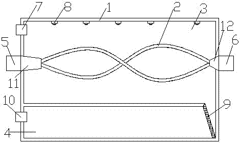
[0006] This product is composed of: 1. Cabinet, 2. Heat exchange tube, 3. Overheating chamber, 4. Recovery chamber, 5. Compressed air inlet, 6. Compressed air outlet, 7. Low pressure air inlet, 8. Spray head, 9 .Filter layer, 10. Low-pressure air outlet, 11. Distributor, 12. Combination
[0007] The energy-saving multiplier includes a box body 1 and a heat exchange tube 2. The box body 1 is square, and the inside of the box body 1 is divided into a superheated bin 3 and a recovery bin 4, which can make the low-temperature gas inside the box body 1 and the overheated gas The gas is separated to ensure that the temperature in the superheated chamber 3 is low. The left side of the superheated chamber 3 is provided with a compressed air inlet 5, and the right side is provided with a compressed air outlet 6. The upper left side of the superheated chamber 3 is provided with a low-pressure air inlet 7. A spray head 8 is set on the top, the recovery bin 4 is located at the lower part ...
PUM
 Abstract
Description
Claims
Application Information
 - R&D Engineer
- R&D Manager
- IP Professional
- Industry Leading Data Capabilities
- Powerful AI technology
- Patent DNA Extraction
Browse by: Latest US Patents, China's latest patents, Technical Efficacy Thesaurus, Application Domain, Technology Topic, Popular Technical Reports.
© 2024 PatSnap. All rights reserved.Legal|Privacy policy|Modern Slavery Act Transparency Statement|Sitemap|About US| Contact US: help@patsnap.com