
Dielectric barrier discharge water treatment device and method

A dielectric barrier discharge and water treatment device technology, which is applied in the field of water treatment devices and dielectric barrier discharge water treatment devices, can solve the problem of low energy efficiency of organic wastewater degradation treatment, poor synergistic effect of water treatment devices, and inability to adapt to organic wastewater treatment, etc. problem, to achieve the effect of stable operation, short time and large specific surface area

Inactive Publication Date: 2014-01-01
TAIYUAN UNIV OF TECH
View PDF3 Cites 46 Cited by
  • Summary
  • Abstract
  • Description
  • Claims
  • Application Information

AI Technical Summary

Benefits of technology

This patented technical effect described in this patents relating to a new type of apparatus for purifying liquids containing harmful or unwanted particulate matter that flows into them quickly without losing their ability to pass on these matters due to insolubility between different phases during processing. It uses special techniques such as air blasting devices, micropores, ion exchange membranes, photoelectronics, and activated carbon carriers to enhance particle movement within the liquid while reducing damage from external factors like sunlight exposure. Additionally, it includes various types of catalyzer systems including transition metals titanium oxide, silver nitrogen, ceramics, zeolites, and others to improve decomposition rates and reduce environmental impact caused by organisms involved in biological processes. Overall, this innovative design improves efficient removal of harmful particulate material in wastewaters.

Problems solved by technology

This patent describes various technical solutions related to treating contaminant aqua effluences from industries like manufacturing industry, agricultural production, and sewage disposal processes. Existing techniques involve expensive equipment, complicated reactors, and limited options for regulation control over these chemistry factors. Therefore there is a demand for improved apparatus designs capable of efficiently decompositing organics in both domestic and public settings.

Method used


Image

  • Dielectric barrier discharge water treatment device and method
  • Dielectric barrier discharge water treatment device and method
  • Dielectric barrier discharge water treatment device and method

Examples


Embodiment Construction

[0022] The present invention will be described in further detail below in conjunction with the accompanying drawings: the present embodiment is implemented on the premise of the technical solution of the present invention, and detailed implementation is provided, but the protection scope of the present invention is not limited to the following embodiments.

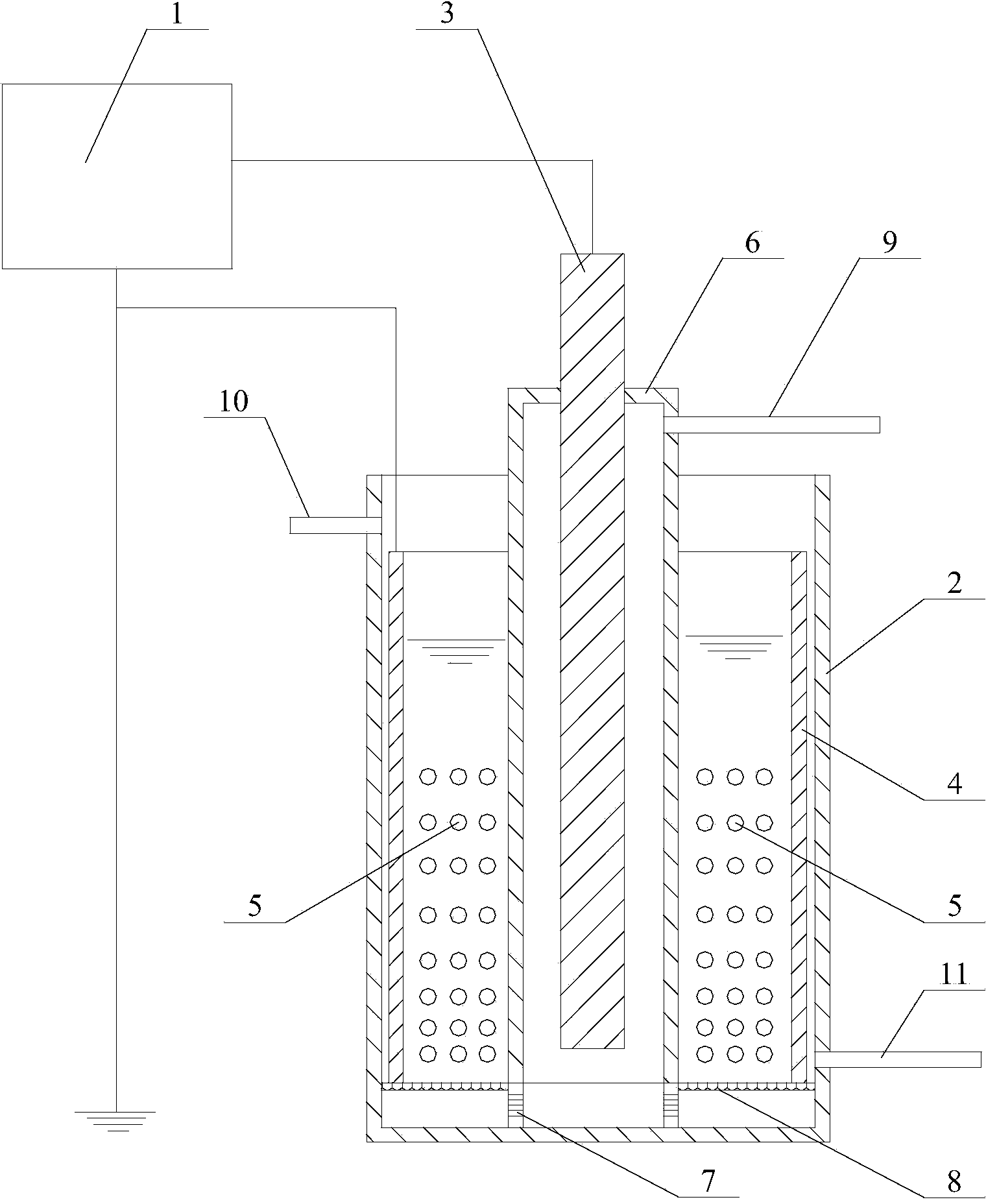
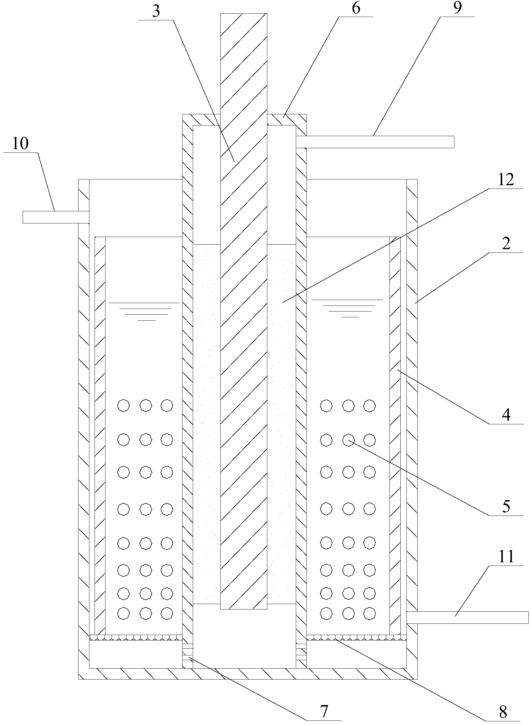
[0023] Such as figure 1 and figure 2 As shown, a dielectric barrier discharge water treatment device involved in this embodiment includes: a high-voltage high-frequency pulse power supply 1, a reactor shell 2, a column-type high-voltage electrode 3, a cylinder-type submerged low-voltage electrode 4, and a vermiculite load Titanium dioxide catalyst 5, medium barrier layer 6 and microporous aeration membrane 8, said medium barrier layer 6 is fixed at the center in the reactor shell 2, the lower end of the medium barrier layer 6 is connected with the bottom in the reactor shell 2 The lower part of the dielectric barrier lay...


PUM


Abstract

The invention provides a dielectric barrier discharge water treatment device and method, belonging to the technical field of a water treatment device and method. The device comprises a high-voltage high-frequency pulse power supply, a reactor shell, a column high-voltage electrode, a cylindrical submerged low-voltage electrode, a vermiculite-supported titanium dioxide catalyst, a dielectric barrier layer and a microporous aeration membrane. The method comprises the following steps: adding a solution to be treated, and applying a high-voltage pulse voltage between the column high-voltage electrode and the cylindrical submerged low-voltage electrode, wherein the peak voltage is 1-100kV, and the frequency is 1-50KHz; and adjusting the inlet air quantity, and regulating the contact time between treated wastewater and active particles inside the reactor. An aerator is introduced into the water treatment device, and medium-activity substances generated by dielectric barrier plasma discharge can completely enter the solution to the treated through the aerator, so the water treatment device has the advantages of high mass-transfer efficiency and short required time; the method is stable in running and simple to operate, and can run under atmospheric pressure; and the equipment is easy to manage and has high practicality and economical efficiency.

Description


Claims


Application Information

Patent Timeline
Owner TAIYUAN UNIV OF TECH
Learn More