Floor blowing machine

A ground machine and air guide tube technology, which is applied to dryers, lighting and heating equipment, drying, etc., can solve the problems of increasing the size of the floor blower, hindering the rotation of the air guide tube, and increasing transportation and storage costs. Achieve the effect of compact overall structure, easy installation and disassembly, and avoid damage

Pending Publication Date: 2017-12-15
JIANGMEN KEYE ELECTRICAL & MECHANICAL MFG CO LTD
View PDF10 Cites 3 Cited by
  • Summary
  • Abstract
  • Description
  • Claims
  • Application Information

AI Technical Summary

Problems solved by technology

[0003] Existing floor blowers with adjustable wind outlet angles include two side walls, an air guide tube, a handle and a motor, and the air guide tube is rotatably arranged between the two side walls, but the handle Installed on two side walls, it will hinder the rotation of the air guide tube. In order to ensure that the rotation of the air guide tube is not restricted, it will inevitably increase the size of the entire floor blower, thereby increasing transportation and storage costs.
In addition, because most of the weight of the floor blower is concentrated on the air guide tube, while the handle is arranged on the side wall, when the floor blower is lifted, it is easy to cause the connection between the side wall and the air guide tube to be overstressed. big and damaged

Method used


Image

  • Floor blowing machine
  • Floor blowing machine
  • Floor blowing machine

Examples


Embodiment Construction

[0023] The technical solution of the present invention will be described in detail below in conjunction with the accompanying drawings. In describing the present invention, it should be understood that the terms "center", "longitudinal", "transverse", "upper", "lower", "front", "rear", "left", "right", " The orientations or positional relationships indicated by "straight", "horizontal", "top", "bottom", "inner" and "outer" are based on the orientations or positional relationships shown in the drawings, and are only for the convenience of describing the present invention and Simplified descriptions, rather than indicating or implying that the device or element referred to must have a particular orientation, be constructed and operate in a particular orientation, and thus should not be construed as limiting the invention. In the description of the present invention, unless otherwise specified, "plurality" means two or more.

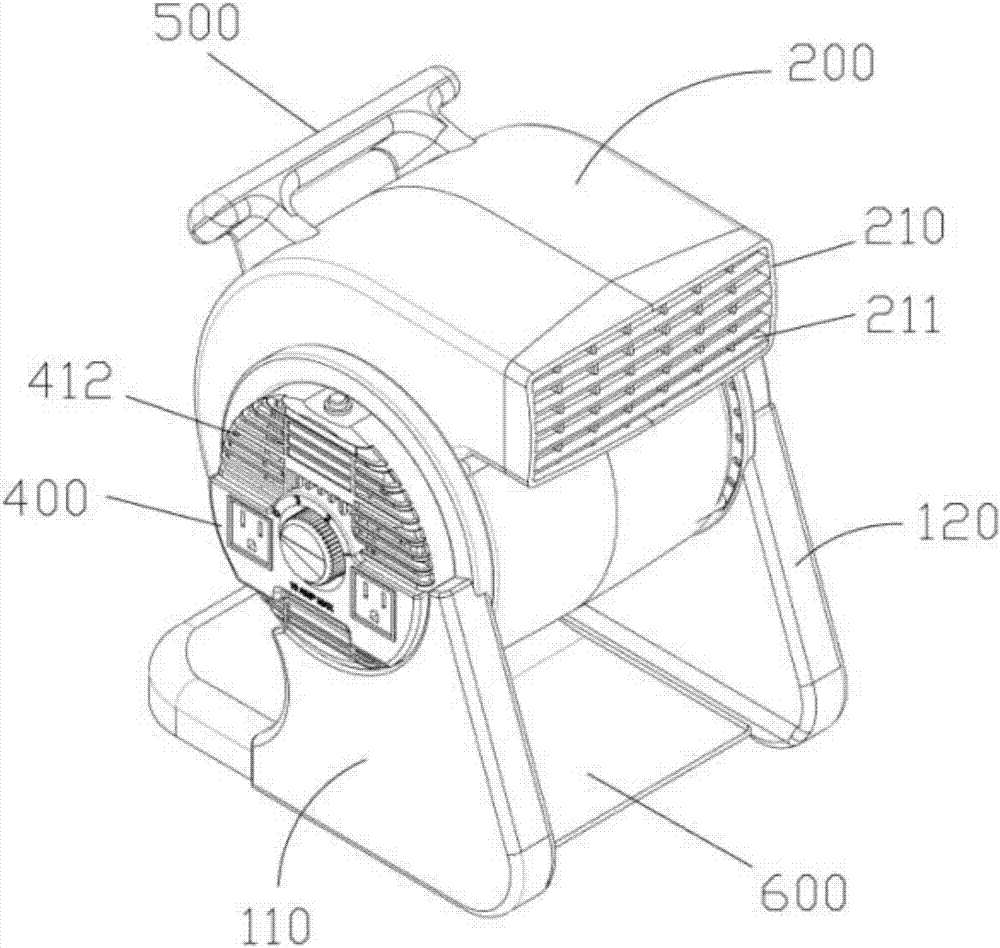
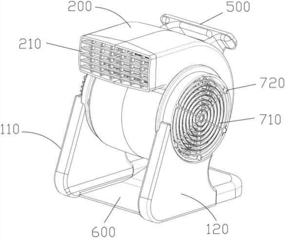
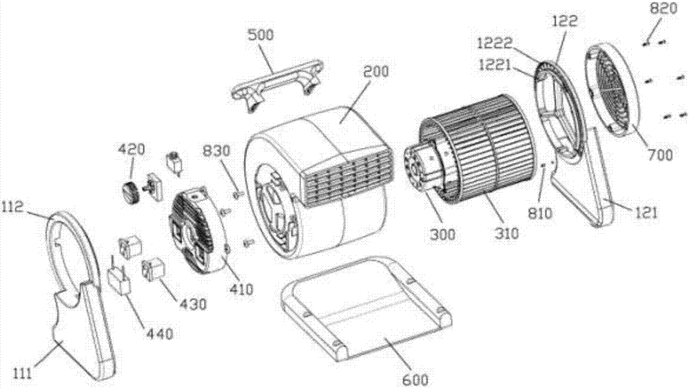
[0024] Please also see figure 1 , figure 2 , im...


PUM


Abstract

The invention relates to a floor blowing machine. The floor blowing machine comprises two side walls, an air guiding barrel, a handle, a motor, a wind wheel and a control assembly. The two side walls are oppositely arranged in parallel. The air guiding barrel is rotatably arranged between the two side walls. The handle is installed on the air guiding barrel. The motor and the wind wheel are both installed in the air guiding barrel. The control assembly is arranged on the side wall on the side close to the motor, and the position where the control assembly and the corresponding side wall are installed is located on the inner side of the corresponding side wall; and the control assembly is electrically connected with the motor. The air-out angle can be adjusted through rotation of the air guiding barrel, better blowing and drying effects are achieved, and the floor blowing machine is compact in overall structure and attractive and durable.

Description

technical field [0001] The invention relates to the technical field of floor blowers, in particular to a floor blower with an adjustable air outlet angle. Background technique [0002] A floor blower is a machine that draws outside air into the machine through the air inlet and blows it out from the air outlet. The floor blower usually has a volute-shaped body, the air outlet is close to the ground, and the body is provided with foot pads, which can be placed on the ground to dry wet places. The body of the existing floor blower is usually integrally formed, and the angle of the air outlet is fixed, but in the process of use, it is often necessary to adjust the air outlet angle to achieve a better drying effect. [0003] Existing floor blowers with adjustable wind outlet angles include two side walls, an air guide tube, a handle and a motor, and the air guide tube is rotatably arranged between the two side walls, but the handle Installed on the two side walls, it will hind...

Claims


Application Information

Patent Timeline
Patent Type & Authority Applications(China)
IPC IPC(8): F26B21/00F26B21/06
CPCF26B21/004F26B21/06
Inventor 何向明林光濂
Owner JIANGMEN KEYE ELECTRICAL & MECHANICAL MFG CO LTD
Why Eureka
Try Eureka