A spreader reducer test system

A test system and reducer technology, applied in the testing of machine/structural components, instruments, and mechanical components, etc., can solve the problems of time consumption, inconvenient installation and disassembly, affecting equipment debugging, delivery schedule, etc., to improve accuracy sexual effect

Active Publication Date: 2019-08-02
GUIZHOU AEROSPACE TIANMA ELECTRICAL TECH
View PDF7 Cites 0 Cited by
  • Summary
  • Abstract
  • Description
  • Claims
  • Application Information

AI Technical Summary

Problems solved by technology

In the previous tests, the no-load and load tests were carried out after the spreader reducer was installed on the equipment. This operation mode is inconvenient to install and disassemble, and consumes time. The equipment may be damaged during the test, and the test needs to be completed after the equipment is assembled. carry out, affecting the commissioning and delivery progress of equipment

Method used


Image

  • A spreader reducer test system
  • A spreader reducer test system
  • A spreader reducer test system

Examples


Embodiment Construction

[0019] The technical solution of the present invention is further described below, but the scope of protection is not limited to the description.

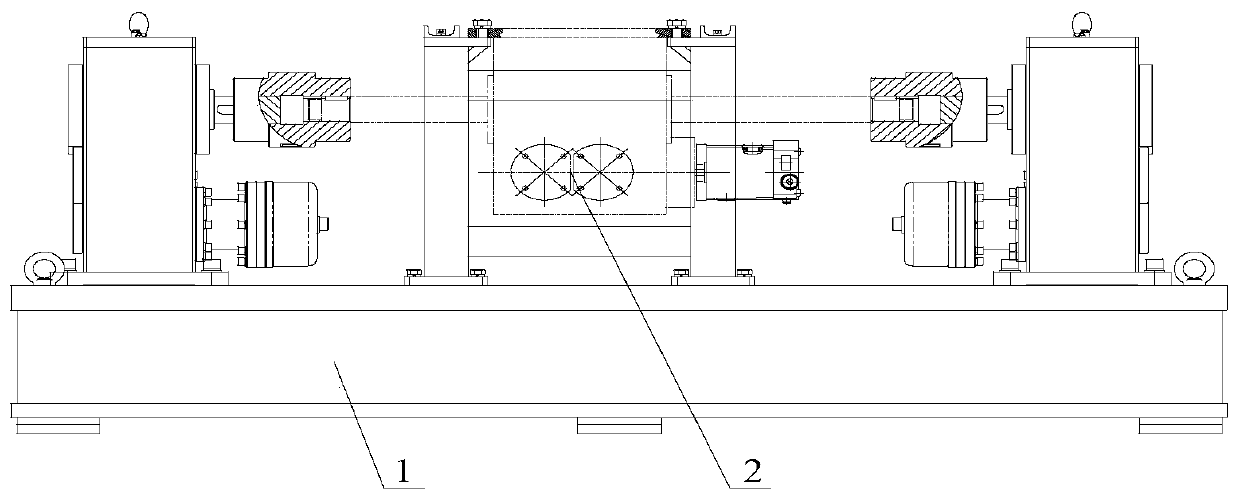
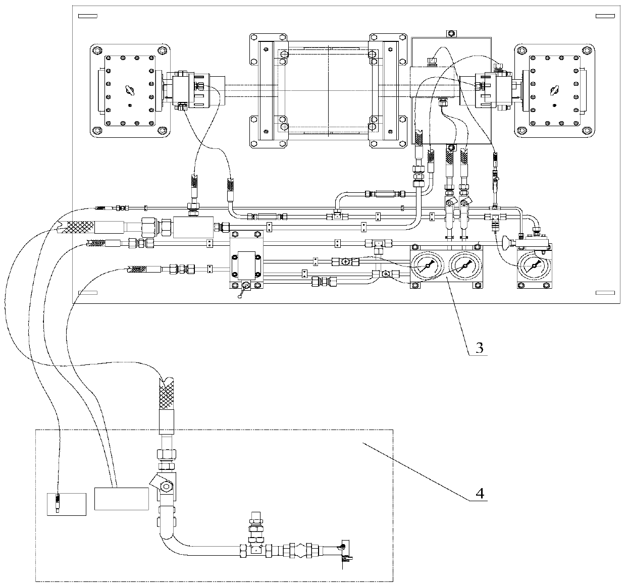
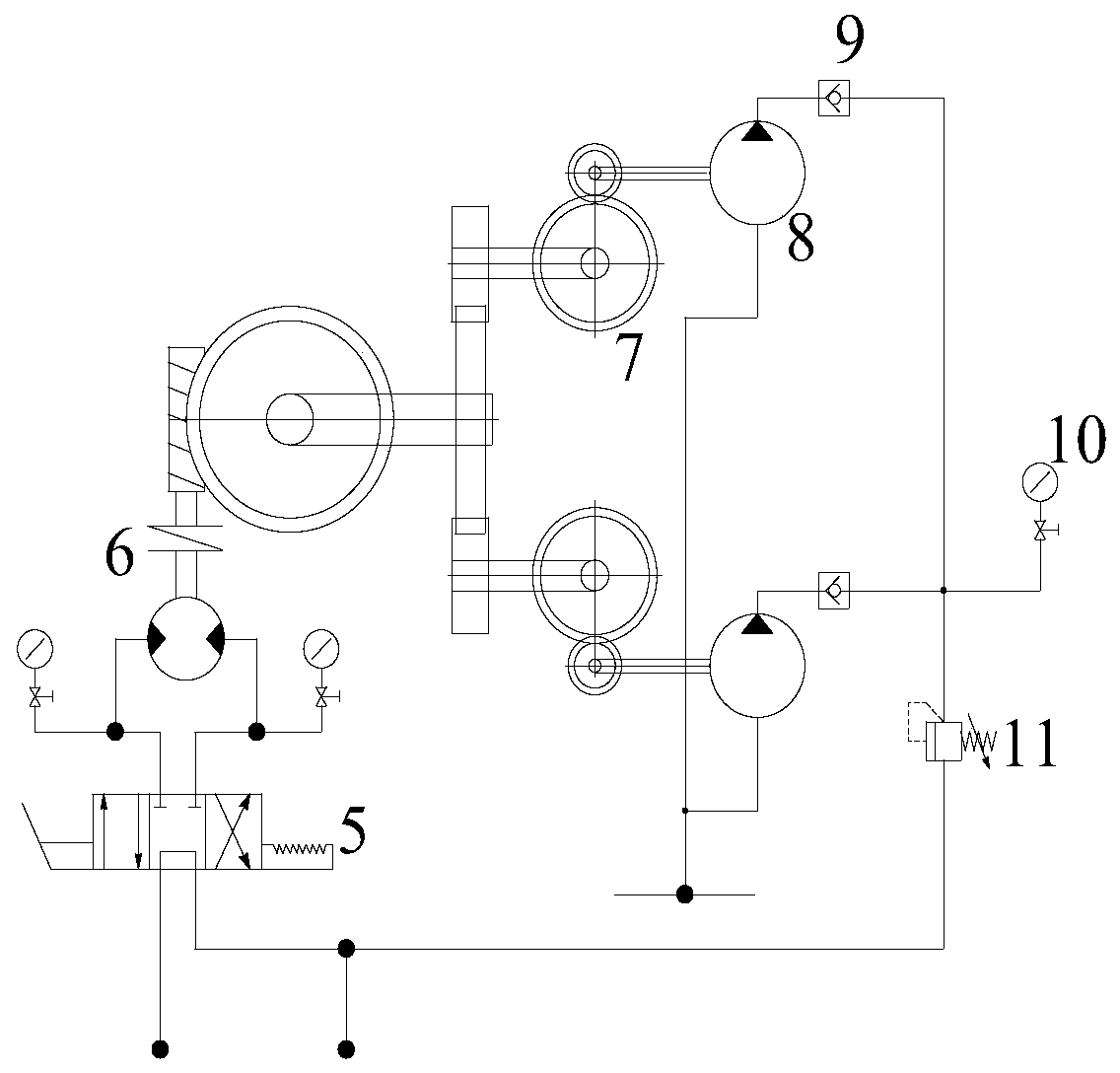
[0020] Such as Figure 1 to Figure 3 The shown test system for a spreader reducer includes a test bench 1, a spreader reducer 2, a hydraulic system 3, and a pump station 4; the spreader reducer 2 and hydraulic system 3 are installed on the test bench 1, and the hanger The reducer 2, the hydraulic system 3 and the hydraulic pipeline of the pump station 4 are connected to form a hydraulic circuit. The hydraulic system 3 has a motor 6 and an RK radial piston pump 8, and the hydraulic circuit controls the motor 6 and the RK radial piston pump 8 respectively. To work, the motor 6 drives the reducer 7 to be tested, and the reducer 7 acts on the RK radial piston pump 8 .

[0021] There are two RK radial piston pumps 8, two RK radial piston pumps 8 are connected to two pipelines, two reducers 7 act on the RK radial piston pumps 8 respecti...


PUM


Abstract

The invention provides a lifting sling reducer test system comprising a test stand, a lifting sling reducer, a hydraulic system and a pump station. The lifting sling reducer and the hydraulic system are installed on the test stand. The lifting sling reducer, the hydraulic system and the pump station hydraulic pipeline are connected to form a hydraulic loop. The hydraulic system is provided with a motor and an RK radial plunger pump. The hydraulic loop controls working of the motor and the RK radial plunger pump. The motor drives a reducer to be tested. The reducer actuates on the RK radial plunger pump. The hydraulic pressure is adopted to provide the power source, and the accuracy, the smoothness and the load distribution uniformity of worm and gear transmitting movement can be enhanced through mutual running-in of the internal tooth surface of the lifting sling reducer so that turning adjustment of the motor can be realized, and the load torque of the lifting sling reducer can be simulated.

Description

technical field [0001] The invention relates to a test system for a speed reducer of a spreader. Background technique [0002] Due to the needs of the company's equipment research and development, it is necessary to design a method of using hydraulic power to provide power source and test the reducer of the spreader. In the previous tests, the no-load and load tests were carried out after the spreader reducer was installed on the equipment. This operation mode is inconvenient to install and disassemble, and consumes time. The equipment may be damaged during the test, and the test needs to be completed after the equipment is assembled. It will affect the commissioning and delivery progress of equipment. Contents of the invention [0003] In order to solve the above technical problems, the present invention provides a spreader reducer test system, the spreader reducer test system uses hydraulic power to provide power source, through the mutual running-in of the spreader red...

Claims


Application Information

Patent Timeline
Patent Type & Authority Patents(China)
IPC IPC(8): G01M13/027G01M13/025
CPCG01M13/025G01M13/027
Inventor 周萍向振文
Owner GUIZHOU AEROSPACE TIANMA ELECTRICAL TECH
Why Eureka
Try Eureka