High-reliability pneumatic feeding mechanism

A feeding mechanism and reliable technology, applied in metal processing equipment, feeding devices, manufacturing tools, etc., can solve the problems of machine equipment damage, low precision, slow withdrawal of feeding plate, etc., to achieve accurate feeding position and work efficiency and reliability improvement effect

Inactive Publication Date: 2017-12-19
天津市斯佳琦机械有限责任公司
View PDF0 Cites 6 Cited by
  • Summary
  • Abstract
  • Description
  • Claims
  • Application Information

AI Technical Summary

Problems solved by technology

The accuracy of this kind of feeding mechanism and feeding method into the punching machine is not high, and the feeding plate is to be extended into the punching machine to discharge the material. If the automatic feeding mechanism makes a small mistake during the conveying process, it will cause the feeding The board exits slowly or gets stuck on the punching machine, and the punching speed is very fast. At this time, the punching device of the punching machine will hit the feeding plate, causing damage to the machine equipment and even endangering the personal safety of the workers.

Method used


Image

  • High-reliability pneumatic feeding mechanism

Examples


Embodiment Construction

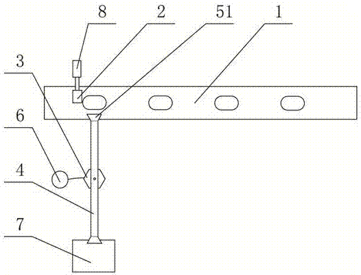
[0010] A specific embodiment of the invention will be described below in conjunction with the accompanying drawings.

[0011] In the figure, 1. conveyor belt; 2. limit block; 3. rotary cylinder; 4. connecting rod; 5. vacuum suction cup; 6. vacuum generator; 7. stamping station; 8. telescopic mechanism.

[0012] Such as figure 1 As shown, the limiting block 2 is located above the conveyor belt 1, the upper end of the rotary cylinder 3 is connected to the middle of the connecting rod 4, the two ends of the connecting rod 4 are respectively provided with the vacuum suction cups 5, the vacuum The suction cup 5 is connected with the vacuum generator 6, and the two ends of the connecting rod 4 are located above the conveyor belt 1 and on the stamping station 7 respectively. The rotation angle of the rotary cylinder 3 is 180°. The limit block 2 can be connected with the telescopic mechanism 8 or the lifting mechanism. In this embodiment, the telescopic mechanism 8 is selected, and ...


PUM


Abstract

The invention discloses a pneumatic feeding mechanism with high reliability, which comprises a conveyor belt, a limit block, a rotary cylinder, a connecting rod, a vacuum suction cup and a vacuum generator, the limit block is located above the conveyor belt, and the upper end of the rotary cylinder Connected to the middle of the connecting rod, the two ends of the connecting rod are respectively provided with the vacuum suction cups, the vacuum suction cups are connected to the vacuum generator, and the two ends of the connecting rod are respectively located above the conveyor belt and the stamping station superior. The beneficial effects of the present invention are: use the limit block to block the material to be processed on the conveyor belt, and play a positioning role for the vacuum suction cup to absorb the material; the role of the rotating cylinder and the vacuum suction cup is equivalent to the role of the manipulator, realizing the pneumatic conveying function of the material, The vacuum suction cup sucks the material, and the rotary cylinder achieves a 180° rotation, and sends the material to the stamping station.

Description

[0001] technical field [0002] The invention belongs to the technical field of mechanical processing equipment, and in particular relates to a highly reliable pneumatic feeding mechanism. Background technique [0003] The traditional feeding mechanism in the stamping machine, such as the cam-driven intermittent feeding mechanism, is prone to scratches or scratches on the surface of the workpiece. Since the cam-driven intermittent feeding mechanism itself is lubricated by oil, it is easy to cause pollution to the workpiece and the environment. The existing automatic feeding mechanism transports the material sheet to the stamping machine for stamping. During the conveying process, the feeding plate of the automatic feeding mechanism will directly transport the material sheet from the storage area to the stamping area with the material sheet. The accuracy of this kind of feeding mechanism and feeding method into the punching machine is not high, and the feeding plate is to ...

Claims


Application Information

Patent Timeline
Patent Type & Authority Applications(China)
IPC IPC(8): B21D43/18B21D43/00
CPCB21D43/18B21D43/003
Inventor 刘怀维
Owner 天津市斯佳琦机械有限责任公司
Why Eureka
Try Eureka