Plasma cutting head with protection function

A protective function and cutting head technology, which is applied in the field of ion cutting machine accessories, can solve problems such as collision damage, reduce the possibility of damage, avoid direct collisions, and achieve good protection effects

Inactive Publication Date: 2017-12-19
湖北敏丰机电设备有限公司
View PDF0 Cites 3 Cited by
  • Summary
  • Abstract
  • Description
  • Claims
  • Application Information

AI Technical Summary

Problems solved by technology

[0004] The purpose of the present invention is to solve the shortcoming that the cutting head body is prone to collision damage during use in the prior art, and propose a plasma cutting head body with protective function

Method used


Image

  • Plasma cutting head with protection function

Examples


Embodiment Construction

[0014] The following will clearly and completely describe the technical solutions in the embodiments of the present invention with reference to the accompanying drawings in the embodiments of the present invention. Obviously, the described embodiments are only some, not all, embodiments of the present invention.

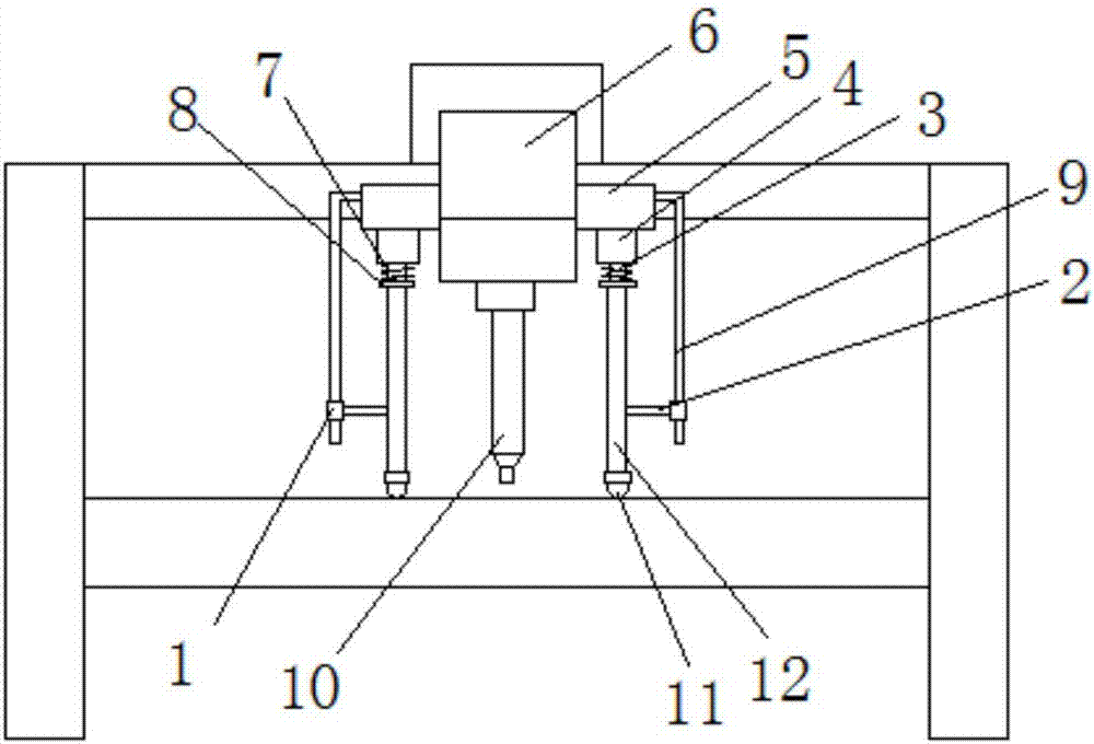
[0015] refer to figure 1 , a plasma cutting head body with protective function, including a cutting head body 10, the cutting head body 10 is installed on the bottom of the driving seat 6, the left and right sides of the driving seat 6 are provided with mounting seats 5, two mounting seats The bottom of 5 is connected with the fixed sleeve 4 that is vertically arranged, and the bottom of fixed sleeve 4 is connected with the insertion rod 3 that is vertically arranged by spring 7, and spring 7 is movably sleeved on the outside of insertion rod 3, and insertion rod 3 The bottom of the sleeve is provided with an annular plate 8 that is connected with the spring 7, and t...


PUM


Abstract

The invention relates to the technical field of plasma cutting machine accessories, in particular to a plasma cutting head body with a protective function, including a cutting head body, the cutting head body is installed on the bottom of a driving seat, and the left and right sides of the driving seat are provided with There are mounting seats, and the bottoms of the two mounting seats are connected with vertical fixed sleeves, the bottoms of the fixed sleeves are connected with the vertically arranged insertion rods through springs, and the springs are movably sleeved on the insertion rods. outside, and the bottom of the plunger is sheathed with an annular plate that fits and connects with the spring. The invention has the advantages of simple structure and convenient use, and can effectively avoid the situation that the cutting head body is damaged due to collision between the cutting head body and the cutting object.

Description

technical field [0001] The invention relates to the technical field of plasma cutting machine accessories, in particular to a plasma cutting head body with a protective function. Background technique [0002] Plasma cutting machine is a machine that processes metal materials by means of plasma cutting technology. Plasma cutting is an advanced cutting processing method, which uses the heat of high-temperature plasma arc to partially or partially melt the metal at the incision of the workpiece, and discharges the molten metal with the momentum of high-speed plasma to form a processing method. [0003] In actual production, the plane of the object to be cut is uneven, and at the same time, the object to be cut will be partially deformed due to the high temperature during the cutting process, which will cause the cutting head to easily collide with the object to be cut, which will seriously damage the cutting head. Contents of the invention [0004] The object of the present ...

Claims


Application Information

Patent Timeline
IPC IPC(8): B23K10/00B23K37/00
CPCB23K10/00B23K37/006
Inventor 吕增智程敏
Owner 湖北敏丰机电设备有限公司
Why Eureka
Try Eureka