
System and method for controlling engine knock of a variable displacement engine

An engine and detonation technology, which is applied in the direction of automatic control of electric motor control, engine components, combustion engines, etc., can solve problems such as difficult detection of engine detonation

Active Publication Date: 2022-01-14
FORD GLOBAL TECH LLC
View PDF19 Cites 0 Cited by
  • Summary
  • Abstract
  • Description
  • Claims
  • Application Information

AI Technical Summary

Problems solved by technology

However, engine knock detection can be difficult even with two engine knock sensors because combustion noise and vibration of the engine block can mask engine knock detectable via the engine knock sensors

Method used


Image

  • System and method for controlling engine knock of a variable displacement engine
  • System and method for controlling engine knock of a variable displacement engine
  • System and method for controlling engine knock of a variable displacement engine

Examples


Embodiment Construction

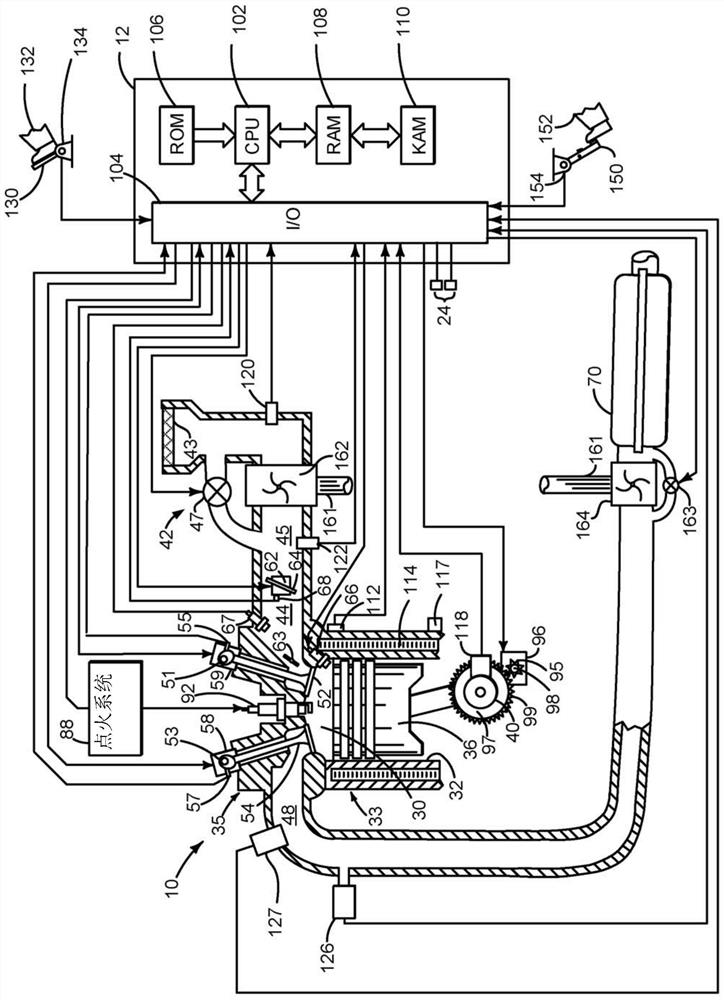
[0061] The present description relates to systems and methods for selectively activating and deactivating cylinders and cylinder valves of an internal combustion engine. The engine can be as Figure 1A to Figure 6D Configure and operate as shown. Various methods and predictive operating sequences for engines involving deactivated valves are in Figure 7 to Figure 42 shown in . Different approaches can work together and with Figure 1A to Figure 6D The system shown operates together.

[0062] refer to Figure 1A , an internal combustion engine 10 comprising a plurality of cylinders, one of which is at Figure 1A shown in . Engine 10 is comprised of cylinder head casting 35 and cylinder block 33 which includes combustion chamber 30 and cylinder walls 32 . Piston 36 is positioned therein and reciprocates via a connection with crankshaft 40 . Flywheel 97 and ring gear 99 are coupled to crankshaft 40 . A starter 96 (eg, a low voltage (operating at less than 30 volts) motor) ...


PUM


Abstract

The present application relates to systems and methods for controlling engine knock of variable displacement engines. Systems and methods for detecting and controlling knock in an engine are presented. In one example, engine knock sensors are selected based on whether certain cylinders are activated and combusting air and fuel or deactivated and not combusting air and fuel. The output of the selected knock sensor is the basis for adjusting the engine spark timing.

Description

[0001] Cross References to Related Applications [0002] This application claims priority to US Provisional Patent Application Serial No. 62 / 347,894, filed June 9, 2016. The entire content of the above application is hereby incorporated by reference in its entirety for all purposes. technical field [0003] The present description relates to systems and methods for controlling engine knock of an engine. The system and method are applicable to engines in which selected engine cylinders may be deactivated via poppet valves. Background technique [0004] The engine may include one or more knock sensors to sense engine knock. In gasoline engines, knocking occurs in the engine after the air-fuel mixture in the cylinder is ignited by the spark. Specifically, the air-fuel mixture is ignited at a location in the cylinder other than the flame front in the cylinder created by the spark. The second ignition after spark ignition is produced by raising the pressure in the cylinder, a...

Claims


Application Information

Patent Timeline
Patent Type & Authority Patents(China)
IPC IPC(8): F02P5/152
CPCF02P5/152F02D41/0087F02D41/0225F02D41/123F02D41/1454F02D41/22F02D41/3094F01L1/181F02P5/045F01L13/0005F02D13/0219F02D13/04F02D13/06F02D17/02F02D35/026F02D35/027F02D37/02F02D41/0002F01L2001/0476F01L2001/0535F01L2001/0537F01L2001/186F01L2013/001F01L2800/00F01L2810/02F02D2041/001F02D2041/0012F02D2041/0015F02D2200/025F02D2200/0406F02D2200/0625F02D2200/101F02D2250/41F01L2820/04F01M1/20F01L2305/00Y02T10/40F02D35/02F02D41/021F02D2041/1433F02D2200/021F02D2200/023F02D2250/18B60W10/06B60W10/10F02D41/26F02D2200/10F02P5/145
Inventor C·P·格卢格拉
Owner FORD GLOBAL TECH LLC
Features
  • Generate Ideas
  • Intellectual Property
  • Life Sciences
  • Materials
  • Tech Scout
  • Unparalleled Data Quality
  • Higher Quality Content
  • 60% Fewer Hallucinations
Learn More