Controlling a vacuum system comprising a vacuum generator

A vacuum generator and vacuum system technology, applied in the field of vacuum systems, can solve complex data management and other problems, and achieve the effect of data management

Inactive Publication Date: 2017-12-19
ピアブアクチエボラグ
View PDF6 Cites 3 Cited by
  • Summary
  • Abstract
  • Description
  • Claims
  • Application Information

AI Technical Summary

Problems solved by technology

[0013] One problem: Sensing vacuum pressure at each suction point requires multiple vacuum sensors, and often complex data management

Method used


Image

  • Controlling a vacuum system comprising a vacuum generator
  • Controlling a vacuum system comprising a vacuum generator

Examples


Embodiment Construction

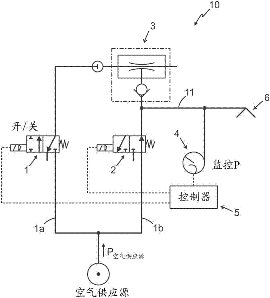
[0025] For a general description of an embodiment of a vacuum system 10 for transporting objects, reference is initially made to figure 1 .

[0026] will now refer to figure 1 An embodiment of the invention is described, wherein details of the embodiment corresponding to the above description of the vacuum system will be given by the previous figure 1 The corresponding reference numerals used in .

[0027] The vacuum system 10 comprises a vacuum generator 3 driven by a flow of compressed air via a first on / off valve 1 or other mechanism for controlling the flow of compressed air, wherein the vacuum generator 3 being part of the vacuum system 10 is arranged in conjunction with One or more vacuum grippers 6 also included in the vacuum system 10 are fluidly connected to supply vacuum to the vacuum grippers 6 due to the flow of compressed air to the vacuum generator 3 . The vacuum system 10 comprises a second valve 2 arranged to be activated (normally opened) and supply compres...


PUM


Abstract

The invention relates to controlling a vacuum system comprising a vacuum generator. A method for controlling a vacuum generator in a vacuum system for transportation of objects, the vacuum system comprises a vacuum generator driven by a compressed air flow via a first on/off valve, a second valve, which is arranged to supply compressed air into the vacuum system, one centralized pressure sensor used for monitoring a system pressure inside the vacuum system and for adaptive blow-off; and a vacuum system controller, wherein if the on/off valve is not flowing air to the vacuum generator, the vacuum system controller indicates a state of no vacuum generation, and the second valve is activated, allowing an amount of compressed air to flow into the vacuum-system for blow-off, blow-off is terminated and excessive air injected into the system is released through the vacuum gripper means, analyzing pressure propagation following blow-off for calculating a duration of when the vacuum system is being fully pressure-equalized in parts of the vacuum gripper means by using a compensation factor.

Description

technical field [0001] The invention relates to a method of controlling a vacuum system comprising a vacuum generator and a controller for a vacuum system comprising a vacuum generator driven by compressed air in order to generate a negative pressure suitable for suction cups or similar devices . Background technique [0002] The present invention relates generally to material handling systems, and more particularly to a material handling system for controlling a vacuum generator for a suction cup of a material handling system that engages an object and substantially passes through a vacuum comprising a vacuum generator and a suction cup. The operation of the system is hermetically sealed. It is known to provide a material handling system comprising suction cups or the like adapted to move and lift and move an object such as a substantially flat object or panel or the like into a desired position. The suction cup can be moved to engage the object, and the vacuum generator ...

Claims


Application Information

Patent Timeline
Patent Type & Authority Applications(China)
IPC IPC(8): F04F5/20F04F5/52
CPCF04F5/20F04F5/52B25J15/0625B65G47/917B25J15/0658B25J15/0633
Inventor 古斯塔夫·威格任彼得·恩格堡
Owner ピアブアクチエボラグ
Why Eureka
Try Eureka