Supercharge Your Innovation With Domain-Expert AI Agents!

Constant velocity universal joint driving shaft assembly

A constant velocity universal joint and universal joint technology, applied in the direction of coupling, elastic coupling, vibration suppression adjustment, etc., can solve the problem of poor controllability of rotation angle, high machining accuracy of ball cage type universal joint, contact stress Large and other problems, to achieve the effect of reducing vibration

Pending Publication Date: 2017-12-19
温州聚泉汽车部件股份有限公司
View PDF9 Cites 1 Cited by
  • Summary
  • Abstract
  • Description
  • Claims
  • Application Information

AI Technical Summary

Problems solved by technology

Existing car drive shafts usually include tripod joints, ball cage joints and intermediate shafts, tripod joints include tripod joint housings, and tripod dustproof Cover, the ball cage type universal joint includes the ball cage universal joint shell, the ball cage assembly and the ball cage dust cover, the tripod dust cover and the end of the ball cage dust cover are respectively lapped on the tripod Joint shell and ball cage universal joint shell, the other ends are respectively fixed on the intermediate shaft, among them, the tripod type universal joint can realize axial movement, and the ball cage type universal joint can realize angular rotation, however , the controllability of the ball cage universal joint to the rotation angle in the prior art is poor, and it cannot satisfy the better drive control of the automobile wheel; the ball cage universal joint has high processing precision, especially the steel ball and the star sleeve. The contact stress is large, and the large gap in the direction of rotation will cause a lot of noise and vibration, which will affect the comfort of the vehicle.

Method used


Image

  • Constant velocity universal joint driving shaft assembly

Examples


Embodiment Construction

[0010] The present invention will be further explained below in conjunction with the accompanying drawings and specific embodiments.

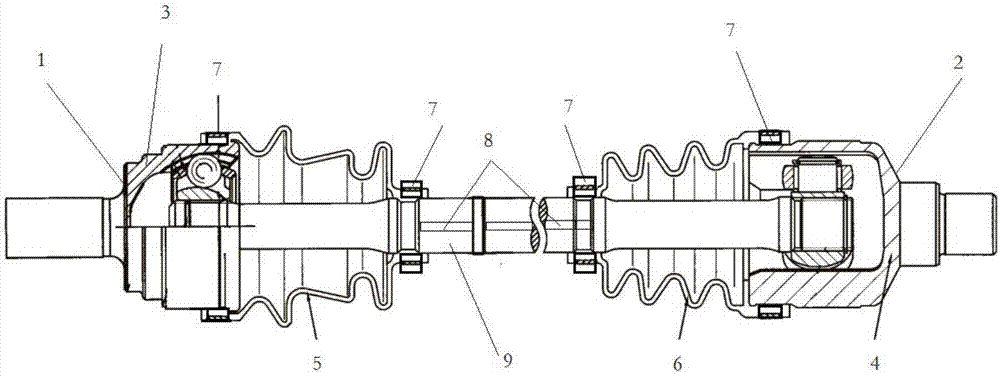
[0011] Such as figure 1 As shown, a constant velocity universal joint drive shaft assembly includes tripod joint 2, ball cage joint 1, intermediate shaft 9, weight block 7 and shock absorbing groove 8, tripod joint The universal joint 2 includes the three-ball universal joint shell 4 and the three-ball pin dust cover 6, the ball cage universal joint 1 includes the ball cage universal joint shell 3 and the ball cage dust cover 5, and the three-ball pin One end of the dust cover 6 and the ball cage dust cover 5 are respectively lapped on the three-ball joint housing 4 and the ball cage joint housing 3, and the other ends are respectively fixed on the intermediate shaft 9, and the three-ball joint A weighted block 7 is provided at the joint between the joint housing 4 and the three-ball pin dust cover 6, and a weighted block 7 is provided at the ...


PUM


Abstract

The invention discloses a constant velocity universal joint driving shaft assembly which comprises a tripod ball type universal joint, a spherical cage type universal joint and an intermediate shaft. The tripod ball type universal joint comprises a tripod ball type universal joint shell and a tripod ball type dustproof cover. The spherical cage type universal joint comprises a spherical cage type universal joint shell and a spherical cage type dustproof cover. One end of the tripod ball type dustproof cover and one end of the spherical cage type dustproof cover are connected to the tripod ball type universal joint shell and the spherical cage type universal joint shell correspondingly in a lap joint manner, and the other end of the tripod ball type dustproof cover and the other end of the spherical cage type dustproof cover are fixed to the intermediate shaft. A weighing block is arranged at the connecting position of the tripod ball type universal joint shell and the tripod ball type dustproof cover, and weighing blocks are arranged at the connecting position of the intermediate shaft and the tripod ball type dustproof cover and the connecting position of the intermediate shaft and the spherical cage type dustproof cover correspondingly. Damping grooves are formed in the middle section of the connecting position, of the spherical cage type universal joint and the spherical cage type universal joint, of the intermediate shaft. The constant velocity universal joint driving shaft assembly is reasonable in structure, low in cost and capable of achieving damping.

Description

technical field [0001] The invention belongs to a constant velocity universal joint drive shaft assembly. Background technique [0002] The car drive shaft is a mechanism that connects two shafts whose axes do not overlap, and makes the two shafts transmit motion at the same angular velocity. Require. Existing car drive shafts usually include tripod joints, ball cage joints and intermediate shafts, tripod joints include tripod joint housings, and tripod dustproof Cover, the ball cage type universal joint includes the ball cage universal joint shell, the ball cage assembly and the ball cage dust cover, the tripod dust cover and the end of the ball cage dust cover are respectively lapped on the tripod Joint shell and ball cage universal joint shell, the other ends are respectively fixed on the intermediate shaft, among them, the tripod type universal joint can realize axial movement, and the ball cage type universal joint can realize angular rotation, however , the controll...

Claims


Application Information

Patent Timeline
IPC IPC(8): F16F15/32F16D3/202F16D3/223F16D3/84B60K17/22
CPCF16D3/202F16D3/223F16D3/843F16F15/322B60K17/22
Inventor 虞品春曹开明王海宇郑利平蔡文龙
Owner 温州聚泉汽车部件股份有限公司
Features
  • R&D
  • Intellectual Property
  • Life Sciences
  • Materials
  • Tech Scout
  • Unparalleled Data Quality
  • Higher Quality Content
  • 60% Fewer Hallucinations
Learn More