Image artifact removing method for digital tomography system

A tomography, digital technology, applied in the field of image processing of medical imaging

Active Publication Date: 2017-12-19
SOUTHERN MEDICAL UNIVERSITY
View PDF5 Cites 3 Cited by
  • Summary
  • Abstract
  • Description
  • Claims
  • Application Information

AI Technical Summary

Problems solved by technology

At present, there is no mature technology to deal with these two types of artifacts

Method used


Image

  • Image artifact removing method for digital tomography system
  • Image artifact removing method for digital tomography system
  • Image artifact removing method for digital tomography system

Examples


Embodiment 1

[0043] Such as figure 1 As shown, a method for removing image artifacts of a digital tomography system includes the following steps:

[0044] A1. Obtain the original projection data y of the digital tomography system.

[0045] The original projection data y is obtained by linear interpolation method to obtain the soft tissue projection data y Tissue .

[0046] The original projection data y is obtained by mutual information entropy or graph cut method to obtain high-attenuation material projection data y HighAtt .

[0047] A2. Segmentation. Segment the original projection data y to obtain high-attenuation material projection data y HighAtt and soft tissue projection data y Tissue .

[0048] A3. Project data y of high attenuation material HighAtt generate mask data y HighAttMask .

[0049] A4, filtering, performing filtering operation on the original projection data y to obtain the filtered projection data y Filtered , and then according to the mask data y HighAttMas...

Embodiment 2

[0069] A method for removing image artifacts of a digital tomography system, other features are the same as in Embodiment 1, the difference is that: taking high-attenuation substances as calcification points as an example, the method includes the following steps:

[0070] A1. Obtain the original projection data y of the digital tomography system.

[0071] A2. Segment the original projection data y to obtain the calcification point projection data y Ca and soft tissue projection data y Tissue .

[0072] A3. Project the calcification point data y Ca Generate calcification point mask data y CaMask .

[0073] A4, filtering, performing filtering operation on the original projection data y to obtain the filtered projection data y Filtered , and then according to the mask data y CaMask The filtered high attenuation material projection data y is extracted from CaFiltered .

[0074] A5. Project soft tissue data y Tissue The soft tissue reconstruction image μTissue is reconstru...

Embodiment 3

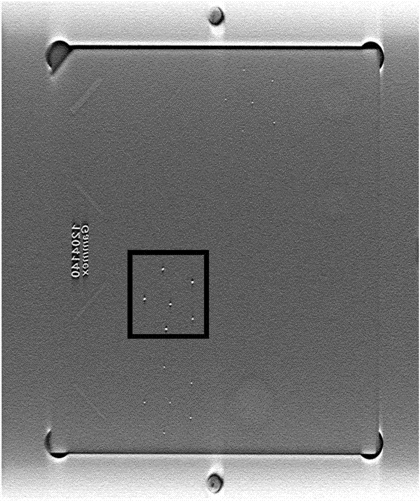
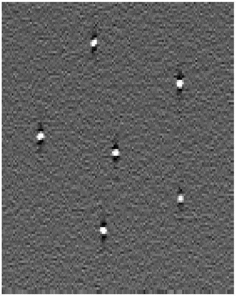
[0085] A method for removing image artifacts of a digital tomography system, other features are the same as in Embodiment 1, the difference is: as figure 1 , Figure 2 and Figure 3, taking the US Cirs015 phantom projection data as an example, the specific implementation process is as follows:

[0086] Obtain the system parameters of the digital tomography equipment, and the original projection data y of the Cirs015 phantom under conventional scanning. The pixel matrix size of the projected image is 2048×1280, the distance from the X-ray source to the rotation center and the detector is 700mm, the rotation angle of the tube is between ± 7.5°, the sampling value is 15, and the flat panel detector, detector The cell size is 70um.

[0087] The original projection data y is reconstructed using the traditional cone beam FDK algorithm, and the filtering process is performed using the Ramp window.

[0088] Figure 2(a) and Figure 2(b) show the reconstructed image of the 37th layer and...


PUM


Abstract

The invention provides an image artifact removing method for a digital tomography system. The method comprises the steps that A1 the original projection data y of the digital tomography system are acquired; A2 the original projection data y are divided; A3 high attenuation material projection data yHighAtt generate mask data yHighAttMask; A4 the original projection data y are filtered; A5 soft tissue projection data yTissue are reconstructed to acquire a soft tissue reconstruction image mu Tissue, and the high attenuation material projection data yHighAttFiltered are reconstructed to acquire a high attenuation material reconstruction image mu HighAtt; and A6 a final image is acquired, and specifically the total high attenuation material reconstruction image mu HighAtt-FreeArtifacts without artifacts and the soft tissue reconstruction image mu Tissue are summated to acquire the final artifact-removed image data mu.

Description

technical field [0001] The invention relates to the technical field of image processing of medical images, in particular to an image artifact removal method of a digital tomography system. Background technique [0002] In the presence of highly attenuating material such as guide needles inserted during biopsy or large clusters of calcifications, severe artifacts can appear in the reconstructed images of digital tomography systems. There are mainly two different types of artifacts. The first type is caused by Stripe artifacts appearing at the edge of high-attenuation materials caused by beam hardening and limited-angle sampling; the second type is high-attenuation material artifacts caused by sampling angle and sampling geometry, that is, high-attenuation materials should only appear in a certain reconstruction image layer, but this high attenuation material also appears in other reconstruction layers, and the geometry of this high attenuation material is distorted in other r...

Claims


Application Information

Patent Timeline
Patent Type & Authority Applications(China)
IPC IPC(8): G06T11/00G06T5/00
CPCG06T5/002G06T11/006G06T11/008
Inventor 马建华王永波曾栋何基边兆英黄静
Owner SOUTHERN MEDICAL UNIVERSITY
Why Eureka
Try Eureka