Injection molding machine injection hydraulic loop achieving high-response injection and injection molding control method of injection molding machine injection hydraulic loop

A technology of hydraulic circuit and control method, which is applied in the field of injection hydraulic circuit of injection molding machine and its injection molding control. It can solve the problems of inability to adjust flow, pressure, poor injection repeatability, and decreased production efficiency, so as to improve production efficiency and improve injection molding. The effect of repeatability and simple structure

Pending Publication Date: 2017-12-22
CHENGDU LIANYU PRECISION MACHINERY
View PDF0 Cites 3 Cited by
  • Summary
  • Abstract
  • Description
  • Claims
  • Application Information

AI Technical Summary

Problems solved by technology

This kind of circuit is to add an accumulator device at the outlet of the oil pump. The injection action is always performed by the pressure oil provided by the accumulator. Since the accumulator itself cannot adjust the flow and pressure, an expensive proportional valve must be used to control the injection cylinder for injection. , and no matter what speed and pressure the actual action requires, the oil pump must first charge the hydraulic oil into the accumulator at the highest pressure, resulting in higher energy consumption
[0004] In addition, because the injection action is always followed by the mold clamping action, the existing injection circuit and its control method will have a process because of the pressure drop after the mold clamping is completed, and this process cannot be exactly the same every time, so If the state of the system pressure oil is different before each injection, it will cause poor injection repeatability. In order to eliminate such deviation, a delay time is often added before injection to wait for the pressure to stabilize, resulting in a decrease in production efficiency

Method used


Image

  • Injection molding machine injection hydraulic loop achieving high-response injection and injection molding control method of injection molding machine injection hydraulic loop
  • Injection molding machine injection hydraulic loop achieving high-response injection and injection molding control method of injection molding machine injection hydraulic loop

Examples


Embodiment Construction

[0023] The technical solutions of the present invention will be described in further detail below with reference to the accompanying drawings, but the protection scope of the present invention is not limited to the following.

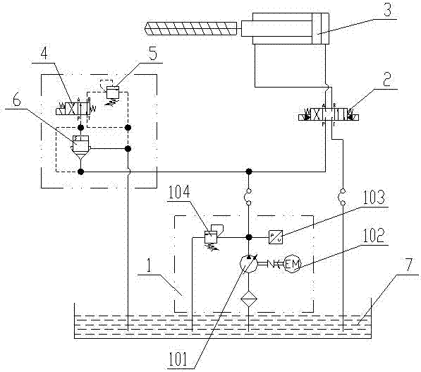
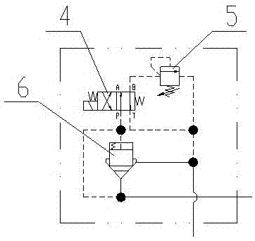
[0024] Such as figure 1 As shown, an injection hydraulic circuit of an injection molding machine for realizing high-response injection includes an injection cylinder 3 and a main oil circuit connected to the injection cylinder 3. The main oil circuit is provided with a hydraulic pump system 1 and a first electromagnetic reversing valve 2, so The injection hydraulic circuit of the injection molding machine described above also includes a control oil circuit, which is composed of a second solenoid valve 4, a second relief valve 5 and a cartridge valve 6. The control oil port of the cartridge valve 6 is connected with the oil inlet, The oil inlet of the installation valve 6 is connected to the oil inlet of the first solenoid directional valve 2 on the main oil...


PUM


Abstract

The invention discloses an injection hydraulic circuit of an injection molding machine for realizing high-response injection and an injection molding control method thereof, which comprises an injection cylinder (3) and a main oil circuit connected to the injection cylinder (3). Including the control oil circuit, the control oil circuit is composed of the second solenoid valve (4), the second overflow valve (5) and the cartridge valve (6). The safety pressure of the hydraulic pump system (1) is P1, and the second solenoid valve ( 4) The working pressure is P2, and P1 is greater than P2. The beneficial effects of the present invention are: by adding a control oil circuit to the oil inlet (pressure oil inlet) of the injection electromagnetic reversing valve, instead of the complicated accumulator in the existing oil circuit, through the overflow valve and the cartridge valve The coordinated actions of the injection molding machine make the system pressure oil of the injection molding machine always maintain a constant pressure and flow rate before injection, so that the injection molding machine can obtain a higher injection molding response during injection molding, and improve the injection repeatability on the basis of reducing equipment energy consumption. Improve the production efficiency of the injection molding machine.

Description

Technical field [0001] The invention relates to an injection hydraulic circuit of an injection molding machine that realizes high-response injection and an injection control method thereof, and belongs to the technical field of mold injection molding machine oil circuit systems. Background technique [0002] The injection response of the injection molding machine refers to the time it takes for the injection speed to accelerate from zero to the maximum during injection. The shorter the time, the better the performance. Especially for the injection molding of thin-walled plastic products, a high injection speed is required. The injection response is a very critical performance index. Generally, a faster injection response makes injection molding easier and requires less clamping force. The traditional injection circuit has no control branch and cannot realize the acceleration before injection. It can only accelerate from zero to the set value after the injection action starts, whi...

Claims


Application Information

Patent Timeline
Patent Type & Authority Applications(China)
IPC IPC(8): B29C45/82
CPCB29C45/82B29C2945/76775
Inventor 张元海陈斌
Owner CHENGDU LIANYU PRECISION MACHINERY
Why Eureka
Try Eureka