Supercharge Your Innovation With Domain-Expert AI Agents!

Beam lifter

A beam lifting machine and main beam technology, which is applied to cranes, trolley cranes, lifting equipment braking devices, etc., can solve the problem of inability to realize active or automatic adjustment of the height of outriggers, inability to apply to construction operations, and complicated luffing structures on both sides, etc. problem, to achieve the effect of simple structure, reasonable structure and stable support

Active Publication Date: 2017-12-22
ZHENGZHOU NEW DAFANG HEAVY IND & TECH
View PDF11 Cites 3 Cited by
  • Summary
  • Abstract
  • Description
  • Claims
  • Application Information

AI Technical Summary

Problems solved by technology

[0002] With the construction of urbanization, the operation connection between adjacent cities and the development of urban rail transit, intercity track beams and subway bridges are used more and more widely. There will be a difference in the height of the road surface, and the width of the station is wider than the normal operating area. For the erection in this working condition, a new erection equipment is required, which can be used on roads with varying slopes and heights, and can meet erection requirements of different widths. To meet the needs of bridge erection
The previous Chinese utility model patent ZL200420060318.0 discloses a bridge erecting machine. The outriggers on both sides of the bridge erecting machine can move left and right along the main girder to realize variable span and variable amplitude, but the structure of variable amplitude on both sides is complicated. The manufacturing cost is relatively high; in addition, although the patent provides a lifting and steering device between the walking box and the outriggers, which can make the walking wheels realize a small range of lifting and steering changes, it cannot achieve effective and large-scale active adjustment of the height of the outriggers. Or automatic adjustment, not suitable for construction operations on the ground with a large height difference

Method used


Image

  • Beam lifter
  • Beam lifter
  • Beam lifter

Examples


Embodiment Construction

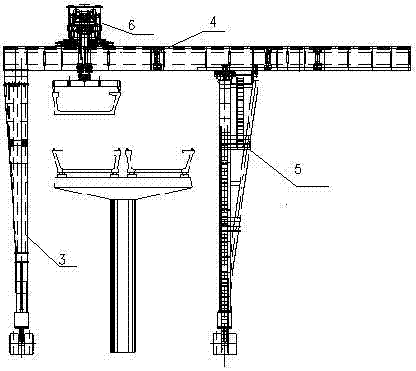
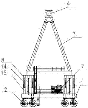
[0024] Such as figure 1 As shown, the beam lifting machine of the present invention can be used for lifting various beam structures or similar heavy objects, especially for intercity rails and subway U beams, and specifically includes: vehicle frame 1, vehicle frame suspension assembly 2, fixed and variable height Outrigger 3, main beam 4, luffing outrigger 5, hoisting mechanism 6, hydraulic system 7. The lower side of the main beam 4 is connected to the fixed outrigger 3, and the other side is connected to the luffing outrigger 5. The main beam is as follows Figure 7 and Figure 8 As shown, it is a single-girder structure, which consists of different segmental beams connected by bolts to form a whole. The upper part of the main beam 4 is provided with two lifting and running tracks 11, and the lower part is provided with two luffing tracks 10. The lifting mechanism 6 is installed with a lifting On the walking track 11, it can move left and right along the main girder. The ...


PUM


Abstract

The invention relates to a beam lifter. The beam lifter structurally comprises a main beam, a car frame, a suspension assembly, a fixing supporting leg, a main beam, an amplitude variation supporting leg, a hoisting mechanism and a hydraulic system; the lower portion of the fixing supporting leg is in rigid connection with the car frame and the suspension assembly on the corresponding side, the upper portion of the fixing supporting leg is in rigid connection with the main beam, the lower portion of the amplitude variation supporting leg is in rigid connection with the car frame and the suspension assembly on the corresponding side, the upper portion of the amplitude variation supporting leg is in flexible connection with the main beam, and the hoisting mechanism is arranged on the main beam and can move left and right along the main beam. The fixing supporting leg and / or the amplitude variation supporting leg have / has the heightening function, active and automatic adjustment of the height of the supporting leg on one side or supporting legs on the two sides can be achieved, the main beam keeps horizontal all the time, the beam lifter can well adapt to the work environment with the large the ground height difference, and stability in the heightening process can be ensured.

Description

technical field [0001] The invention relates to a beam lifting machine, in particular to a beam lifting machine for intercity rails and subway bridge U girders. Background technique [0002] With the construction of urbanization, the operation connection between adjacent cities and the development of urban rail transit, intercity track beams and subway bridges are used more and more widely. There will be a difference in the height of the road surface, and the width of the station is wider than the normal operating area. For the erection in this working condition, a new erection equipment is required, which can be used on roads with varying slopes and heights, and can meet erection requirements of different widths. To meet the needs of bridge erection. The previous Chinese utility model patent ZL200420060318.0 discloses a bridge erecting machine. The outriggers on both sides of the bridge erecting machine can move left and right along the main girder to realize variable span...

Claims


Application Information

Patent Timeline
Patent Type & Authority Applications(China)
IPC IPC(8): B66C19/00B66C5/02
CPCB66C5/02B66C19/00
Inventor 张志华陈永久孙海丽陈媛媛王琪苏春霞刘元宝程波崔瑞玲贾力锋牛青林祖国栋白康
Owner ZHENGZHOU NEW DAFANG HEAVY IND & TECH
Features
  • R&D
  • Intellectual Property
  • Life Sciences
  • Materials
  • Tech Scout
  • Unparalleled Data Quality
  • Higher Quality Content
  • 60% Fewer Hallucinations
Learn More