Floating clamping jaw self-adapting to bricking stack

A floating gripper, self-adaptive technology, applied in the direction of the lifting device, etc., can solve the problems that affect the loading and unloading efficiency, and the clamping device cannot adapt to the shape of the brick stack, so as to reduce the floating resistance and increase the floating amount.

Active Publication Date: 2017-12-22
SICHUAN COLLEGE OF ARCHITECTURAL TECH
View PDF14 Cites 1 Cited by
  • Summary
  • Abstract
  • Description
  • Claims
  • Application Information

AI Technical Summary

Problems solved by technology

[0004] The purpose of the present invention is to provide a floating gripper for self-adaptive bricklaying piles, which is used to solve the problem that the clamping device of the bricklaying machine in the prior art cannot adapt to the shape of the bricklaying pile and can only be manually adjusted by the operator of the power car. Problems Affecting Loading and Unloading Efficiency

Method used


Image

  • Floating clamping jaw self-adapting to bricking stack
  • Floating clamping jaw self-adapting to bricking stack
  • Floating clamping jaw self-adapting to bricking stack

Examples


Embodiment 1

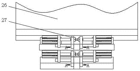
[0032] combined with Figure 1-6 As shown, a kind of floating jaw of self-adaptive bricklaying pile comprises the L-shaped hanger 1 that connects successively, floating device 2, clamping device 3; Said floating device 2 comprises the base 26 that is connected with hanger 1, Slide the linear floating plate 24 that is arranged on the base 26, rotate the circular rotary floating plate 22 that is arranged on the linear floating plate 24 and is connected with the clamping device 3; The tightening direction is parallel, and the side of the linear floating plate 24 parallel to the sliding direction of the linear floating plate 24 has a first limiting block 241 ; the base 26 is provided with a first clamping mechanism for clamping and releasing the first limiting block 241 .

[0033]In this embodiment, the hanger 1 is connected with a forklift. The clamping device 3 adopts the clamp disclosed in Chinese patent CN201210296238.4: it includes two clamping arms arranged opposite to each...

Embodiment 2

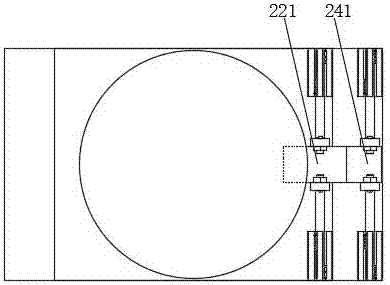
[0037] In order to better implement the present invention, the clamping device 3 can adapt to the floating of the bricklaying stack 4 along the vertical axis rotation direction. On the basis of Embodiment 1, combined with the attached Figure 1-6 Further, the rotation axis of the rotary floating plate 22 is perpendicular to the end surface of the linear floating plate 24, and the outer circular surface of the rotary floating plate 22 has a second limit block 221; The second clamping mechanism of the two limit blocks 221.

Embodiment 3

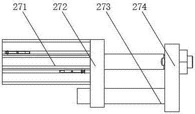
[0039] For implementing the present invention better, increase the floating amount of linear floating plate 24, on the basis of embodiment 1, in conjunction with attached Figure 1-6 Further, the first clamping mechanism is two linear mechanisms 27 with the same structure and symmetrically arranged on both sides of the first limit block 241 along the sliding direction parallel to the linear floating plate 24; the linear mechanism 27 includes a 26 fixedly connected to the oil cylinder mounting plate 272, the oil cylinder 271 detachably connected to the oil cylinder mounting plate 272, and the push block 274 fixedly connected to the piston rod of the oil cylinder 271 to push the first limit block 241 to move.


PUM


Abstract

The invention discloses a floating clamping jaw self-adapting to a bricking stack and relates to the field of clamping devices. The floating clamping jaw comprises a hanging frame, a floating device and a clamping device which are sequentially connected. The floating device comprises a base connected with the hanging frame, a linear floating plate slidably arranged on the base and a circular rotating floating plate which is rotatably arranged on the linear floating plate and connected with the clamping device. The sliding direction of the linear floating plate is parallel to the clamping direction of the clamping device, and a first limiting block is arranged on the side face, parallel to the sliding direction of the linear floating plate, of the linear floating plate; the base is provided with a first clamping mechanism for clamping and loosening the first limiting block; the rotating axis of the rotating floating plate is perpendicular to the end face of the linear floating plate, and the outer circle face of the rotating floating board is provided with a second limiting block; and a second clamping mechanism for clamping and loosening the second limiting block is arranged on the linear floating plate. The clamping device of a brick clamping machine can be self-adapted to tightly clamp floating in the direction of the bricking stack, and manually adjustment of an operator of a power vehicle for the clamping device is not needed.

Description

technical field [0001] The invention relates to the field of gripping devices, in particular to a floating gripper for self-adaptive bricklaying stacks. Background technique [0002] At present, more and more manufacturers use fly ash, quicklime, gravel, sand and other raw materials to make building bricks. Since the finished bricks produced are generally stacked on autoclaved trolleys, the finished bricks placed on each autoclaved trolley The quantity and placement method are exactly the same. In addition, most brick factories have a large output (generally 100,000 to 150,000 per day), and the finished bricks are placed on autoclaved trolleys, requiring too many autoclaved trolleys, which increases production costs. The finished bricks need to be unloaded from the autoclave trolley. [0003] Chinese patent CN201210296238.4 discloses a clamping device and a brick holding machine using the device. The clamping device includes a hanger and a hanger hinged on the top of the ha...

Claims


Application Information

Patent Timeline
Patent Type & Authority Applications(China)
IPC IPC(8): B66F9/18B66F9/22
CPCB66F9/188B66F9/22
Inventor 王旭东
Owner SICHUAN COLLEGE OF ARCHITECTURAL TECH
Why Eureka
Try Eureka