
Optical glass small strip material molding device

A technology of optical glass and forming device, which is applied in glass forming, glass reshaping, glass manufacturing equipment, etc. It can solve problems such as inability to draw strips, reduce glass cutting processes, avoid adhesion, and uniform glass cold lines small effect

Active Publication Date: 2017-12-22
HUBEI NEW HUAGUANG NEW INFORMATION MATERIALS CO LTD
View PDF9 Cites 4 Cited by
  • Summary
  • Abstract
  • Description
  • Claims
  • Application Information

AI Technical Summary

Problems solved by technology

In this method, the position of the mold bottom plate, side plate and plugging device is fixed, and the temperature is high during production. If the glass is drawn at a high speed, the glass liquid will adhere to the mold bottom plate, side plate, plugging device and glass liquid if the cooling time is insufficient. , so this method cannot draw narrower strips

Method used


Image

  • Optical glass small strip material molding device
  • Optical glass small strip material molding device
  • Optical glass small strip material molding device

Examples


Embodiment Construction

[0020] Various exemplary embodiments, features, and aspects of the invention will be described in detail below with reference to the accompanying drawings. The same reference numbers in the figures indicate functionally identical or similar elements. While various aspects of the embodiments are shown in drawings, the drawings are not necessarily drawn to scale unless specifically indicated.

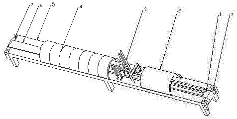
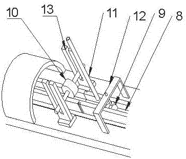
[0021] Examples such as figure 1 As shown, the present invention provides an optical glass strip forming device, which includes a transmission mechanism 1 , a preheating part 2 , a forming part 3 and an annealing part 4 . The preheating section 2 , forming section 3 and annealing section 4 are respectively located at the head end, middle end and end of the transmission mechanism 1 . The transmission mechanism 1 is composed of a frame body 5, a roller 7, a conveyor belt 6 and a power device. There is a roller 7 at each end of the frame body 5, and the conveyor belt 6 is installed on the ...


PUM


Abstract

The invention discloses an optical glass small strip material molding device, and belongs to the technical field of optical glass molding. The optical glass small strip material molding device solves the problems that optical glass forming devices in the prior art cannot overcome production instability and low yield rate caused by mold sticking and deformation of small strip material glass. The optical glass small strip material molding device is characterized in that the optical glass small strip material molding device comprises a transmission mechanism, a preheating part, a forming part and an annealing part, wherein the transmission mechanism comprises a frame body, a roller, a conveyer belt and a power device; the preheating part, the forming part and the annealing part are respectively located at the front end, the middle end and the terminal end of the transmission mechanism; the conveying belt is provided with a forming groove which passes through the preheating part, the forming part and the inner cavity of the annealing part, molten glass moves synchronously with the forming groove when molded in the forming part, and the upper surface can be leveled by a rolling wheel. Small strip material glass with the end surface with the side length of 5 mm or more can be drawn, the optical glass small strip material molding device has the advantages of small and uniform cold marks and high forming consistency, by use of the thin square material, the cutting process of large blocks of glass can be saved, excess glass material and loss are less, and labor cost is low.

Description

technical field [0001] The invention belongs to the technical field of optical glass molding, in particular to a small optical glass strip molding device. Background technique [0002] Optical glass products are the main materials used to make optical lenses and optical instruments. Glass manufacturers first draw the glass into sheets or squares, and the sheets or squares are made into small pieces by cutting, crushing, electric frying, etc., and then processed by pressing to make lenses of appropriate size, and finally the terminal Optical product manufacturers assemble these lenses into optical lenses or instruments. In the above process, the utilization rate is only about 75% due to the excess material and loss in the process of making small pieces of sheet or square material, so the cost of finished lenses is relatively high. In order to improve the utilization rate and reduce the cost, some ordinary optical glass adopts the method of pressing to improve the utilizat...

Claims


Application Information

Patent Timeline
Patent Type & Authority Applications(China)
IPC IPC(8): C03B23/00
CPCC03B23/0093
Inventor 陈超李建新王拓周希光寇小勇
Owner HUBEI NEW HUAGUANG NEW INFORMATION MATERIALS CO LTD
Learn More