
Rotating type spotlight

A technology of rotating and rotating brackets, which is applied in the direction of lampshades, damage prevention measures for lighting devices, cooling/heating devices for lighting devices, etc., and can solve problems such as poor heat dissipation, limited angle of adjustment, and dust adhesion to lamps and lanterns. , to achieve the effect of simple structure, increasing the adjustment angle and increasing the convection space

Inactive Publication Date: 2017-12-22
RUGAO LANTU KNITTING CLOTHING CO LTD
View PDF0 Cites 2 Cited by
  • Summary
  • Abstract
  • Description
  • Claims
  • Application Information

AI Technical Summary

Problems solved by technology

[0002] The spotlight is a typical modern lighting with no main lamp and no fixed scale. It can create an indoor lighting atmosphere. If a row of small spotlights are combined, the light can change into wonderful patterns. Because the small spotlights can freely change the angle, the combination The effect of lighting is also ever-changing. The light of the spotlight is soft, elegant and luxurious. It can also be partially illuminated to enhance the atmosphere. In order to meet the changing requirements of the lighting angle, the traditional spotlight will set a rotating shaft on the lamp shell, so that the inside of the shell The lighting part can swing at a certain angle along the rotating shaft to meet the requirements of the lighting angle. However, among the lamps with adjustable angles on the market at present, their structural design is basically symmetrical adjustment at both ends, and the adjustment angle is limited to a certain extent. Moreover, Due to the long-term use of the lamp, dust will adhere to the surface of the lamp, which is difficult to clean. In addition, the use of the bulb will generate heat. If it cannot dissipate heat well, it will reward the service life of the lamp. Therefore, further improvement is needed

Method used


Image

  • Rotating type spotlight
  • Rotating type spotlight

Examples


Embodiment Construction

[0017] The preferred embodiments of the present invention will be described below in conjunction with the accompanying drawings. It should be understood that the preferred embodiments described here are only used to illustrate and explain the present invention, and are not intended to limit the present invention.

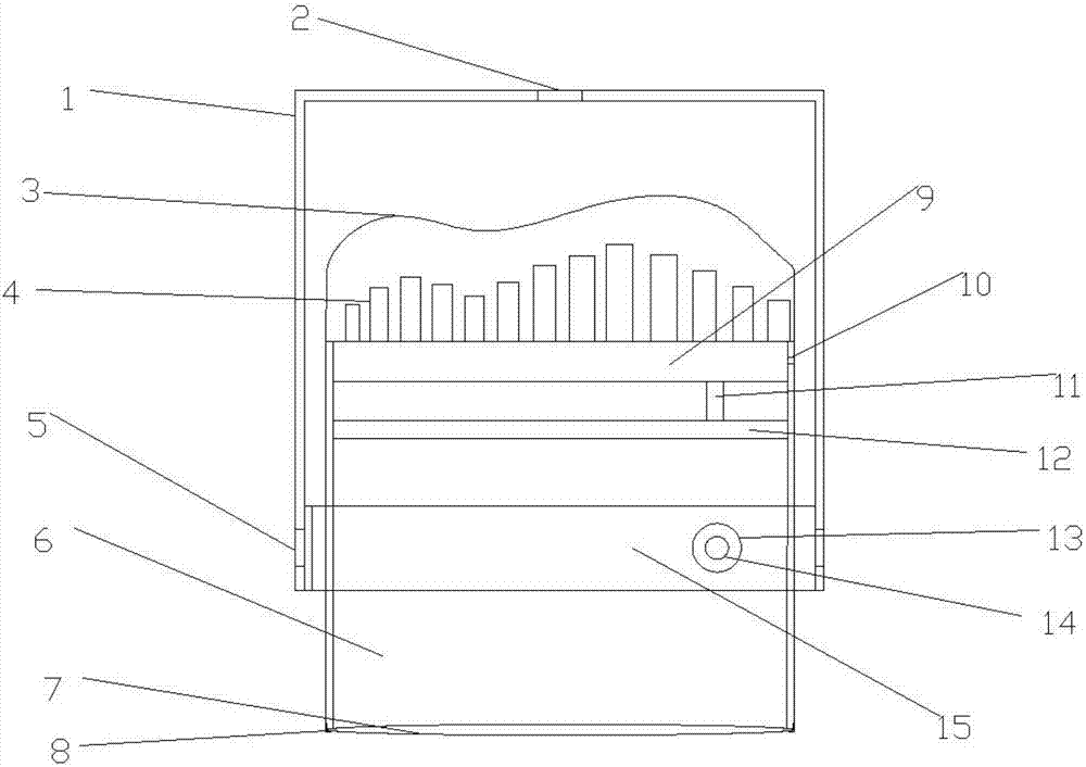
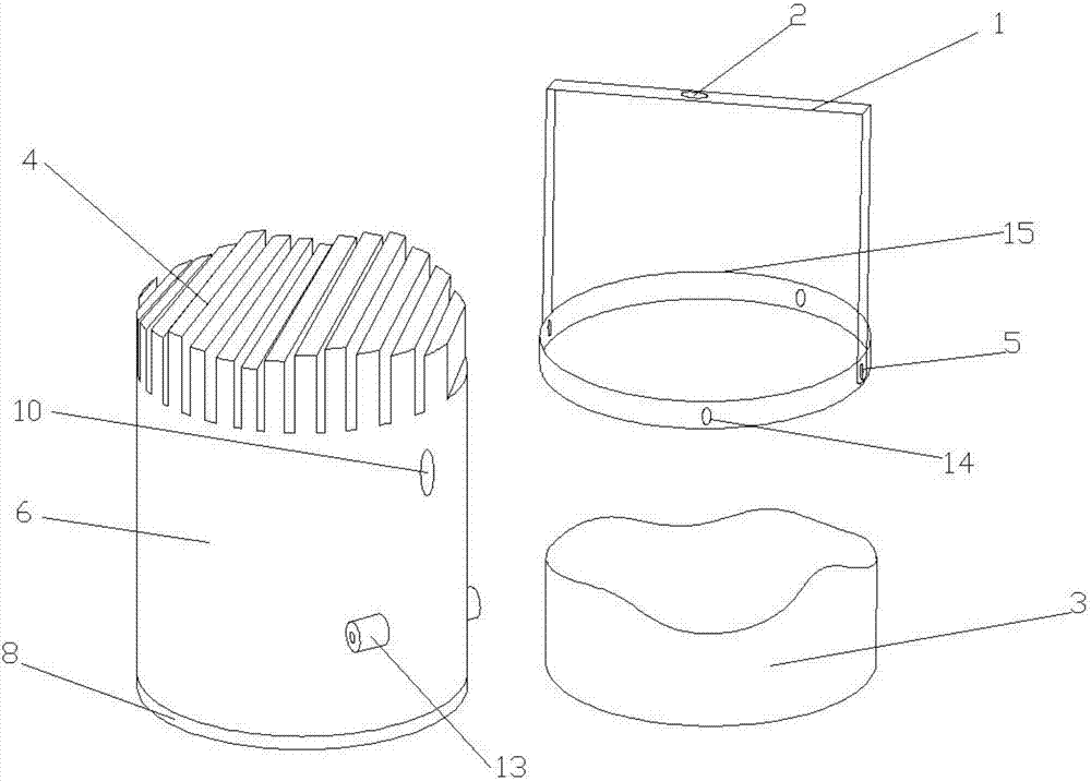
[0018] Such as Figure 1-Figure 2 As shown, a rotary spotlight includes a casing 6. The casing 6 is circular with openings up and down. The bottom of the casing 6 is connected to a clamping shell 8 through threaded rotation. The inner wall of the clamping shell 8 is provided with a high-definition transparent Optical mirror 7, the inner wall of the housing 6 is sequentially provided with a circuit board 9, a circuit channel 11 and a light source 12 from top to bottom, the circuit board 9 and the light source 12 are connected through the circuit channel 11, and the top of the housing 6 A cooling fin 4 and a dustproof cover 3 are provided, and the cooling fin 4 is arr...


PUM


Abstract

A rotary spotlight involved in the present invention includes a shell, the shell is circular with openings up and down, the bottom of the shell is screwed and connected to a clamping shell, and the inner wall of the clamping shell is provided with a high-definition light-transmitting mirror. The inner wall of the housing is sequentially provided with a circuit board, a circuit channel and a light source from top to bottom, the circuit board and the light source are connected through the circuit channel, a heat sink and a dust cover are provided on the top of the housing, and the The heat sink is arranged in the inner cavity of the dustproof cover, and one side of the shell is symmetrically provided with a cylindrical fixing frame, and one side of the cylindrical fixing frame is provided with a first rotating bracket, and one side of the first rotating bracket is symmetrical There is a first rotating bracket interface, and the first rotating bracket interface is set at the connection between the first rotating bracket and the cylindrical fixed frame. The structure is simple, the design is reasonable, and the adjustment angle of the lamp is increased so that the lamp can Good lighting effect can be achieved in the environment, and the heat dissipation effect is better.

Description

technical field [0001] The invention relates to a rotary spotlight, which belongs to the field of lamps. Background technique [0002] The spotlight is a typical modern lighting with no main lamp and no fixed scale. It can create an indoor lighting atmosphere. If a row of small spotlights are combined, the light can change into wonderful patterns. Because the small spotlights can freely change the angle, the combination The effect of lighting is also ever-changing. The light of the spotlight is soft, elegant and luxurious. It can also be partially illuminated to enhance the atmosphere. In order to meet the changing requirements of the lighting angle, the traditional spotlight will set a rotating shaft on the lamp shell, so that the inside of the shell The lighting part can swing at a certain angle along the rotating shaft to meet the requirements of the lighting angle. However, among the lamps with adjustable angles on the market at present, their structural design is basica...

Claims


Application Information

Patent Timeline
IPC IPC(8): F21S8/00F21V21/30F21V29/74F21V17/12F21V3/04F21V15/01
CPCF21S8/00F21V3/10F21V15/01F21V17/12F21V21/30F21V29/74
Inventor 袁德梅
Owner RUGAO LANTU KNITTING CLOTHING CO LTD
Learn More