Positive pressure value control method, device, system and equipment unit in different rooms

A control method and room technology, applied in heating and ventilation control systems, mechanical equipment, lighting and heating equipment, etc., can solve the problems of fixed equipment unit functions and inability to flexibly adjust the positive pressure of each room, and achieve the effect of reducing later costs

Active Publication Date: 2019-08-06
GREE ELECTRIC APPLIANCES INC
View PDF7 Cites 0 Cited by
  • Summary
  • Abstract
  • Description
  • Claims
  • Application Information

AI Technical Summary

Problems solved by technology

[0008] In the embodiment of the present invention, a method, device, system and equipment unit for controlling positive pressure values ​​in different rooms are provided to solve the problem in the prior art that the functions of the equipment unit are fixed and the positive pressure of each room cannot be flexibly adjusted

Method used


Image

  • Positive pressure value control method, device, system and equipment unit in different rooms
  • Positive pressure value control method, device, system and equipment unit in different rooms
  • Positive pressure value control method, device, system and equipment unit in different rooms

Examples


Embodiment 1

[0042] In the embodiment of the present invention, the manual control panel of the indoor room is compatible with the automatic control system, thereby realizing the control and adjustment of positive pressure values ​​in multiple rooms. The automatic control scheme and the manual control scheme are introduced respectively below.

[0043] 1. Automatic control scheme

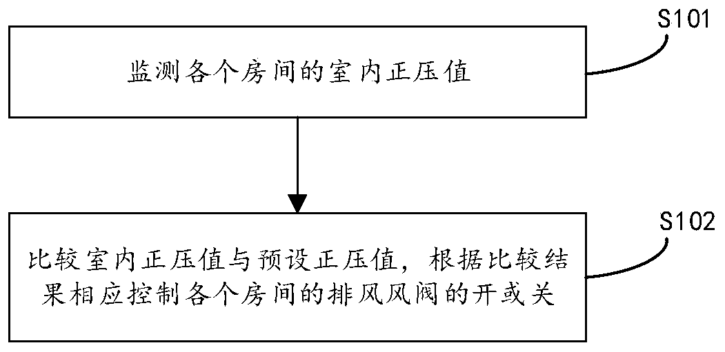
[0044] figure 1 It is a flowchart of an automatic control method for positive pressure values ​​in different rooms according to an embodiment of the present invention, such as figure 1 As shown, the method includes the following steps:

[0045] Step S101, monitoring the indoor positive pressure value of each room;

[0046]Step S102, comparing the indoor positive pressure value with the preset positive pressure value, and correspondingly controlling the opening or closing of the exhaust dampers of each room according to the comparison result.

[0047] Through this embodiment, the automatic control and adjustme...

Embodiment 2

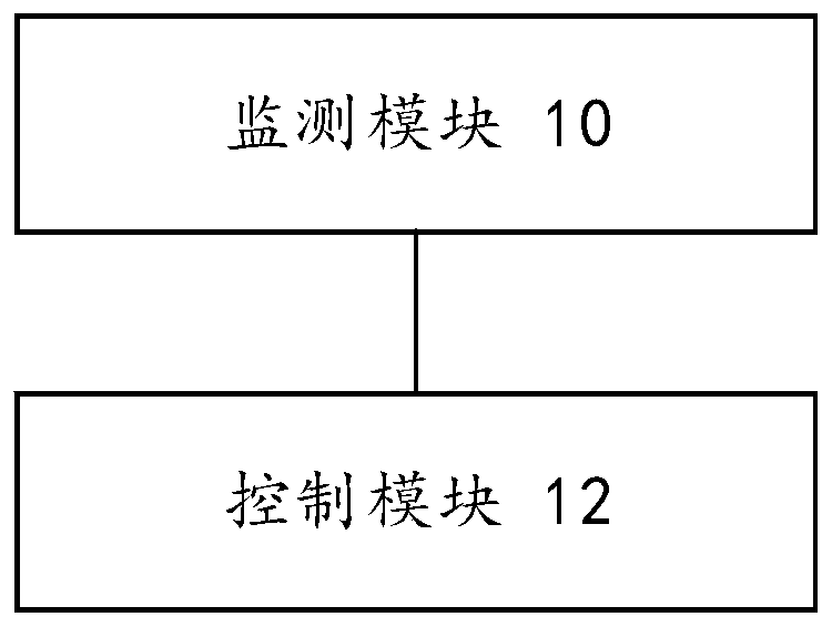
[0065] corresponds to figure 1 Introducing the automatic control method for positive pressure values ​​in different rooms, this embodiment provides an automatic control device for positive pressure values ​​in different rooms, such as image 3 The structural block diagram of the automatic control device for positive pressure values ​​in different rooms shown, the device includes:

[0066] Monitoring module 10, for monitoring the indoor positive pressure value of each room;

[0067] The control module 12 is connected to the monitoring module 10, and is used for comparing the indoor positive pressure value with the preset positive pressure value, and correspondingly controlling the opening or closing of the exhaust air valves of each room according to the comparison result.

[0068] Through this embodiment, the automatic control and adjustment of the positive pressure values ​​in different rooms is realized, and there is no need to temporarily change the room according to the d...

Embodiment 3

[0087] Figure 5 It is a structural schematic diagram of different room positive pressure value control systems according to an embodiment of the present invention, such as Figure 5As shown, the system includes: pressure sensors arranged in each room, air supply damper (electric air supply damper S), exhaust damper (electric exhaust damper P), and a controller; wherein, the pressure sensor , to monitor the indoor positive pressure value of each room; the controller is used to compare the indoor positive pressure value with the preset positive pressure value, and control the opening or closing of the exhaust air valve of each room according to the comparison result; Both the wind damper and the exhaust damper are closed. Based on this, automatic control and adjustment of positive pressure values ​​in different rooms can be realized. Figure 5 In the illustration, pressure sensors and interactive panels are set in each room as an example.

[0088] In order to realize the man...


PUM


Abstract

The invention discloses a control method, device and system for positive pressure values of different rooms and a device unit. The method includes the steps that an instruction for adjusting the positive pressure values is received, and the to-be-adjusted positive pressure value of each room is confirmed according to the instruction; and the positive pressure values are compared with room original positive pressure values, and exhaust air valves of the rooms are correspondingly controlled to be opened or closed according to comparison results. By means of the control method, device and system for the positive pressure values of the different rooms and the device unit, the control manner that manual control panels of the indoor rooms are compatible with an automatic control system is added, the positive pressure values of the different rooms are controlled and adjusted in an automatic and manual switching manner, there is no need to temporarily change the rooms according to different requirements, positive pressure control and later-period room adjustment of the multiple rooms are achieved, and the later-period cost is reduced.

Description

technical field [0001] The invention relates to the field of unit technology, in particular to a method, device, system and equipment unit for controlling positive pressure values ​​in different rooms. Background technique [0002] Commonly used combined air conditioning units only provide a certain amount of air volume, and do not have the function of distributing the positive pressure values ​​required by different rooms, nor can they flexibly change the positive pressure values ​​of the rooms. There is a problem that the room functions are fixed and cannot be flexibly adjusted. [0003] The disadvantages of the above-mentioned commonly used combined air-conditioning units mainly include: [0004] 1) It cannot provide the positive pressure value of different rooms, or even change the function of the room; [0005] 2) The positive pressure air supply function cannot be switched manually; [0006] 3) It cannot isolate dust, bacteria and other pollutants in the air, which m...

Claims


Application Information

Patent Timeline
Patent Type & Authority Patents(China)
IPC IPC(8): F24F11/32F24F11/64F24F11/88
Inventor 彭延君和中元代成
Owner GREE ELECTRIC APPLIANCES INC
Why Eureka
Try Eureka