Front double-hydraulic-cylinder wind power blade automatic mold closing device

A mold clamping device and wind blade technology, which is applied to household appliances, other household appliances, household components, etc., can solve the problems of large space occupation, large space occupation, and increased factory cost, and achieve uniform load distribution, simple assembly, and The effect of simple structure

Pending Publication Date: 2022-05-13
TONGJI UNIV
View PDF10 Cites 0 Cited by
  • Summary
  • Abstract
  • Description
  • Claims
  • Application Information

AI Technical Summary

Problems solved by technology

However, this device takes up a lot of space under the steel frame, and needs to be replaced with a steel frame that matches the phase. It cannot be used well with the original steel frame of the factory, which greatly increases the cost of the factory.
At the same time, the equipment has a hydraulic cylinder located under the steel frame, which is not conducive to the later maintenance of the hydraulic cylinder and increases the difficulty of later maintenance
At the same time, this type of equipment occupies a large space outside the steel frame.

Method used


Image

  • Front double-hydraulic-cylinder wind power blade automatic mold closing device
  • Front double-hydraulic-cylinder wind power blade automatic mold closing device
  • Front double-hydraulic-cylinder wind power blade automatic mold closing device

Examples


Embodiment 1

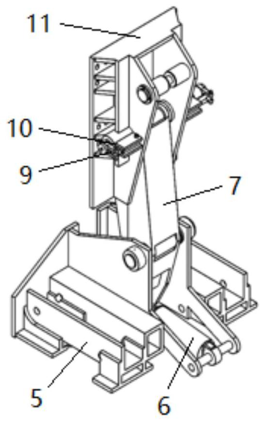
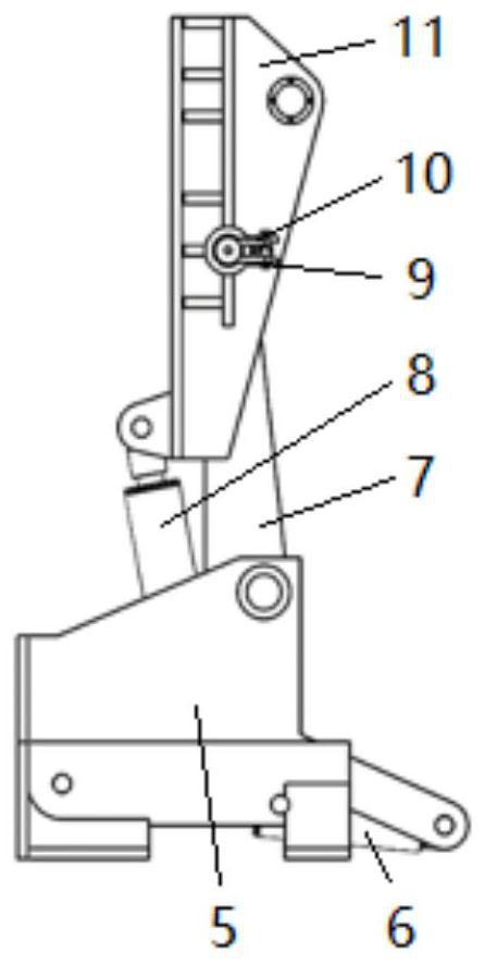
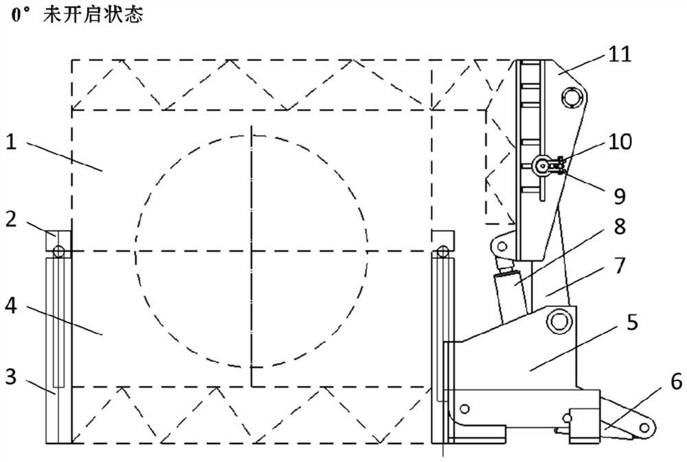
[0046] An automatic mold clamping device for wind blades with front double hydraulic cylinders, including an upper mold 1 and a lower mold 4 for making wind turbine blades, such as Figure 1-6 As shown, it also includes an overturning mechanism fixed on the base 5; the upper mold 1 and the lower mold 4 are arranged on one side of the base 5; the overturning mechanism includes a main hydraulic cylinder 6, a main rocker arm 7, an auxiliary hydraulic cylinder 8 and an auxiliary rocker arm 11 ; The main hydraulic cylinder 6 is fixed on the base 5, and the output end is connected to the main rocker arm 7; the main rocker arm 7 is connected to the base 5 in rotation; 11 transmission connection; the auxiliary rocker arm 11 is rotationally connected with the main rocker arm 7; the upper mold 1 is fixed on the auxiliary rocker arm 11, and the lower mold 4 is fixed on the base 5;

[0047] In the initial state, the upper mold 1 and the lower mold 4 are in the mold closing state;

[0048...

Embodiment 2

[0062] An automatic mold clamping device for wind blades with front double hydraulic cylinders, including an upper mold 1 and a lower mold 4 for making wind turbine blades, such as Figure 7-12 As shown, it also includes an overturning mechanism fixed on the base 5; the upper mold 1 and the lower mold 4 are arranged on one side of the base 5; the overturning mechanism includes a pair of main hydraulic cylinders 6, main rocker arms 7, auxiliary hydraulic cylinders 8 and auxiliary rockers arm 11; a connection plate is fixed on the base 5; the main hydraulic cylinder 6 is symmetrically fixed on the bottom plate on both sides of the connection plate, and the output end is connected to the main rocker arm 7; the main rocker arm 7 is connected to the connection plate in rotation; the auxiliary hydraulic cylinder The cylinder 8 is rotatably connected to the main rocker arm 7, and the output end is connected to the auxiliary rocker arm 11; the auxiliary rocker arm 11 is rotatably conne...


PUM


Abstract

The invention relates to a wind power blade automatic mold closing device, in particular to a front double-hydraulic-cylinder wind power blade automatic mold closing device which comprises an upper mold and a lower mold which are used for manufacturing wind power generator blades and further comprises a turnover mechanism fixed to a base. The upper die and the lower die are arranged on one side of the base; the turnover mechanism comprises a main hydraulic cylinder, a main rocker arm, an auxiliary hydraulic cylinder and an auxiliary rocker arm; the output end of the main hydraulic cylinder is in transmission connection with the main rocker arm; the main rocker arm is rotationally connected with the base; the output end of the auxiliary hydraulic cylinder is in transmission connection with the auxiliary rocker arm; the auxiliary rocker is rotationally connected with the main rocker; the upper die is fixed on the auxiliary rocker arm, and the lower die is fixed on the base. Compared with the prior art, on the premise of ensuring the reliability, the brand-new automatic overturning and mold closing device for the wind power blade is provided from the perspectives of being stable in stress, saving space and reducing the later maintenance difficulty.

Description

technical field [0001] The invention relates to an automatic mold clamping device for wind blades, in particular to an automatic mold clamping device for wind blades with front double hydraulic cylinders. Background technique [0002] Wind blades are one of the core components of wind turbines, accounting for about 15%-20% of the total cost of wind turbines. The quality of their design will directly affect the performance and benefits of wind turbines. Wind blades are mainly lifted and flipped by mechanical cranes to realize demoulding and mold closing, but the process is discontinuous, the movement is not stable, the matching accuracy of the upper and lower molds is poor, and when the center of gravity of the blade mold passes through the center of rotation, there will be a large Vibrations and shocks are likely to cause safety accidents; in addition, manual control is difficult and the productivity is low. The automatic flip mold clamping device works smoothly and can be ...

Claims


Application Information

Patent Timeline
Patent Type & Authority Applications(China)
IPC IPC(8): B29C33/28B29L31/08
CPCB29C33/28B29L2031/082
Inventor 李梦如胡金忠周才波陈哲
Owner TONGJI UNIV
Why Eureka
Try Eureka