
A wind blade automatic flip mold clamping device

A technology of automatic flipping and mold clamping device, which is applied to household appliances, other household appliances, household components, etc. It can solve the problems of unstable movement, discontinuous flipping process, and easy to generate large impact, so as to save workshop space and load Evenly distributed, avoiding the effect of fluctuations

Active Publication Date: 2020-04-07
SHANDONG SHUANGYI TECH
View PDF6 Cites 1 Cited by
  • Summary
  • Abstract
  • Description
  • Claims
  • Application Information

AI Technical Summary

Problems solved by technology

[0002] The main production method of wind blades is to lift and flip the blade mold by mechanical driving to complete demoulding and clamping. However, the flipping process of this method is discontinuous and the movement is not stable, especially when the center of gravity of the blade mold passes through the center of rotation, it will cause relatively large Large vibrations and shocks are likely to cause safety accidents; in addition, manual control is more difficult and productivity is lower
In contrast, the automatic flip mold clamping device is driven by a hydraulic system, which works smoothly and can be automated. In addition, thanks to the standardization of hydraulic components, the cost of the entire system can be controlled within an acceptable range. However, the current mainstream automatic The overturning device adopts two symmetrically arranged oil cylinders, which will encounter a dead point during the overturning process, which needs to be overcome by switching the working state of the two oil cylinders, and it is easy to cause a large impact at the moment of changing the working state; in addition, the two symmetrically arranged oil cylinders occupy more space. Big
[0003] Patent CN201042834Y discloses a megawatt-level wind turbine blade clamping device, which is used to open and close the first female mold and the second female mold during the blade manufacturing process. The base of the first female mold is a fixed base, and the second female mold The mold base is a movable base with a turning device and a locking device, and the turning device is at least two racks connecting the fixed base and the movable base at intervals, and each rack includes a fixed bracket and a rotating bracket pinned to the fixed bracket , the fixed bracket is fixedly connected with the fixed base, the rotating bracket is fixedly connected with the movable base, the rotation and swing of the rotating bracket can realize the closing and opening of the first female mold and the second female mold; the locking device is set on the circumference of the female mold to realize For the locking device after the first female mold and the second female mold are closed, the flipping device and the locking device can be driven by hydraulic pressure, but the device is prone to produce a large impact at the moment of switching the working state, the load distribution is uneven, and the space occupied is relatively large. Big

Method used


Image

  • A wind blade automatic flip mold clamping device
  • A wind blade automatic flip mold clamping device
  • A wind blade automatic flip mold clamping device

Examples


Embodiment Construction

[0024] The present invention will be described in detail below in conjunction with the accompanying drawings and specific embodiments.

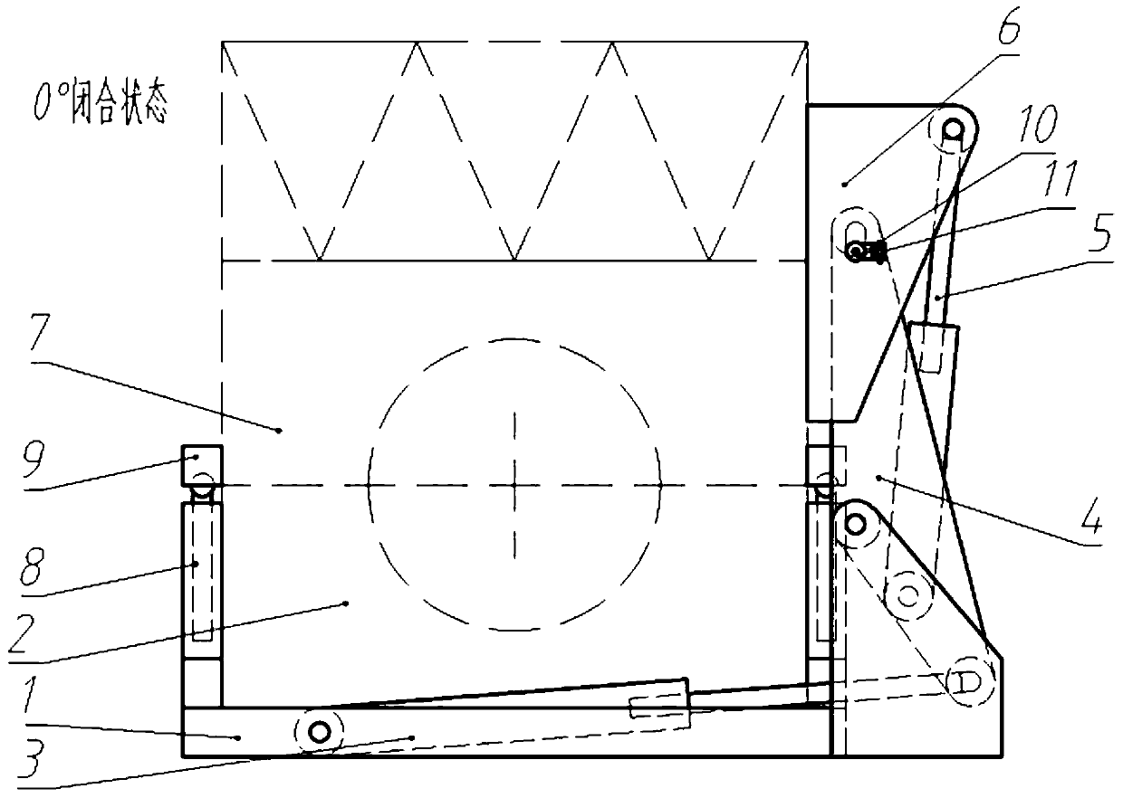
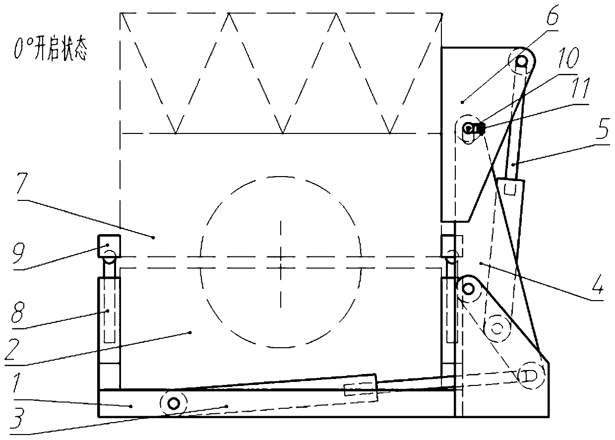
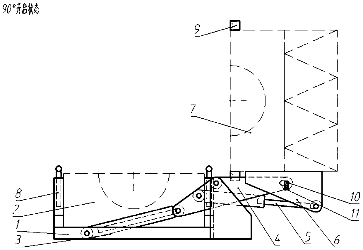
[0025] Such as Figure 1-4 , an automatic flipping mold clamping device for wind blades, used for the manufacture of wind turbine blades, the device includes a fixed lower mold 2, and a reversible upper mold 7, the upper and lower molds can be opened and closed by flipping and moving in translation. The turning mechanism is composed of main hydraulic cylinder 3, auxiliary hydraulic cylinder 5, main rocker arm 4, and auxiliary rocker arm 6. The main hydraulic cylinder 3, main rocker arm 4 and lower mold 2 are installed on the base 1, and the auxiliary hydraulic cylinder 5 is installed on the On the main rocker arm 4, the auxiliary rocker arm 6 is installed on the upper mold 7; the translation mechanism is mainly composed of a jacking hydraulic cylinder 8 and a hemispherical seat 9, the hemispherical seat 9 is installed on both sides of the upp...


PUM

PropertyMeasurementUnit
heightaaaaaaaaaa

Abstract

The invention relates to a wind blade automatic turning and mold closing device. The wind blade automatic turning and mold closing device comprises a base, a lower mold fixedly arranged on the base, and a turnover upper mold movably arranged at the upper part of the lower mold through a turnover mechanism, wherein the turnover mechanism comprises a main hydraulic cylinder, an auxiliary hydraulic cylinder, a main rocker arm, and an auxiliary rocker arm; the main hydraulic cylinder is fixedly arranged on the base; the main rocker arm is rotatably arranged on the base and is connected to the output end of the main hydraulic cylinder in a transmission manner; the auxiliary rocker arm is fixedly arranged on the side of the upper mold; one end of the auxiliary hydraulic cylinder is rotatably arranged on the main rocker arm; the output end of the auxiliary hydraulic cylinder is connected to the auxiliary rocker arm in a transmission manner; a positioning mechanism for positioning the relativeposition of the upper mold and the lower mold is also arranged on the main rocker arm; and a positioning hole matched with the positioning mechanism is also formed in the auxiliary rocker arm. The wind blade automatic turning and mold closing device has high reliability and stable stress and saves space.

Description

technical field [0001] The invention belongs to the technical field of wind blade manufacturing, and in particular relates to an automatic overturning mold clamping device for wind blades. Background technique [0002] The main production method of wind blades is to lift and flip the blade mold by mechanical driving to complete demoulding and clamping. However, the flipping process of this method is discontinuous and the movement is not stable, especially when the center of gravity of the blade mold passes through the center of rotation, it will cause relatively large Large vibrations and impacts are likely to cause safety accidents; in addition, manual control is more difficult and productivity is lower. In contrast, the automatic flip mold clamping device is driven by a hydraulic system, which works smoothly and can be automated. In addition, thanks to the standardization of hydraulic components, the cost of the entire system can be controlled within an acceptable range. H...

Claims


Application Information

Patent Timeline
Patent Type & Authority Patents(China)
IPC IPC(8): B29C33/28B29L31/08
CPCB29C33/28B29L2031/085
Inventor 李梦如李明哲林新栋陈哲奚鹰
Owner SHANDONG SHUANGYI TECH
Learn More