Stacked boiler and closed steam generator
A steam generator and stacked technology, applied in the field of stacked water boilers and closed steam generators, can solve the problems of low heat exchange efficiency and high post-processing costs, and achieve fuel saving, post-cost savings, and heat exchange efficiency. improved effect
- Summary
- Abstract
- Description
- Claims
- Application Information
AI Technical Summary
Problems solved by technology
Method used
Image
Examples
Embodiment 1
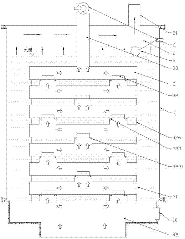
[0034] Such as figure 1 with Figures 4 to 7As shown, the structure of a stacked water pot is disclosed in this embodiment. The water pot includes a pot body 1 , and a water holding chamber 2 and a smoke circulation chamber 3 surrounded by the water holding chamber 2 are arranged in the pot body 1 . A water level control switch 9 is arranged in the water holding chamber 2, and in this embodiment, the water level control switch 9 is a float switch. A steam pipe 21 communicates with the upper end of the water holding chamber 2 . When the water in the water storage chamber 2 decreases, the water inlet pipe connected to the water storage chamber is automatically controlled by the water level control switch 9 to replenish the water in the water storage chamber. The flue gas circulation chamber 3 is formed by stacking several layers of heating chambers 31 and communicating with each other through vent holes 32 . According to the temperature of the flue gas that supplies heat to ...
Embodiment 2
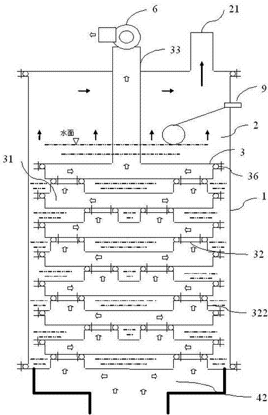
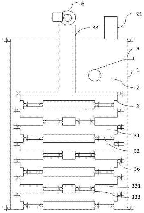
[0040] Such as figure 2 , image 3 , Figure 8 , Figure 9 with Figure 10 As shown, a stacked water pot is also disclosed in this embodiment. The difference between this embodiment and the first embodiment lies in that the structure and stacking method of the heating cavity 31 are different. In this embodiment, the heating chamber 31 is composed of an upper side and a lower side. A protective cover 34 is disposed inside the vent hole 32 , the protective cover 34 is in an inverted T shape and is made of a high temperature resistant material, the high temperature resistant material is alumina ceramic, mullite or silicon carbide material. The upper end of the protective cover 34 is provided with a clamp spring 35, and the clamp spring 35 is clamped on the lower side of the heating cavity 31 located above. During the working process, on the two adjacent heat supply chambers 31, a platform I321 protruding downward is formed around each vent hole 32 on the lower side of the ...
Embodiment 3
[0042] Such as Figure 1 to Figure 13 As shown, this embodiment provides the technical solution of the closed steam generator including the laminated water pot described in the first or second embodiment. In this embodiment, the application of the stacked water pot in Embodiment 1 to the closed steam generator is described in detail.
[0043] In addition to the above-mentioned stacked water pot, the closed steam generator also includes a stove device, which includes a stove body 4 and a fan 5, and the fan 5 communicates with the air inlet area 41 of the stove body 4 through an air duct. , the air intake area 41 is located at the lowermost end of the stove body 4 . The air inlet area 41 is also connected to the peripheral gas source. The uppermost end of the stove body 4 is a hearth area 42 . The stove body 4 is provided with the air intake area 41 , the mixing area 43 , the combustion area 44 and the furnace area 42 sequentially from bottom to top. The outer edge of the bo...
PUM
 Abstract
Description
Claims
Application Information
 - R&D
- Intellectual Property
- Life Sciences
- Materials
- Tech Scout
- Unparalleled Data Quality
- Higher Quality Content
- 60% Fewer Hallucinations
Browse by: Latest US Patents, China's latest patents, Technical Efficacy Thesaurus, Application Domain, Technology Topic, Popular Technical Reports.
© 2025 PatSnap. All rights reserved.Legal|Privacy policy|Modern Slavery Act Transparency Statement|Sitemap|About US| Contact US: help@patsnap.com


