
Automatic cleaning device for boiler scale

An automatic cleaning and boiler scale technology, applied in the control of fluid heaters, lighting and heating equipment, fluid heaters, etc., can solve the problems of increased later costs, laborious cleaning, boiler accidents, etc., to prevent water vapor explosion and reduce later stages. Cost, effect of preventing explosion

Pending Publication Date: 2022-03-15
杨君
View PDF3 Cites 0 Cited by
  • Summary
  • Abstract
  • Description
  • Claims
  • Application Information

AI Technical Summary

Problems solved by technology

[0003] After the boiler is used for a long time, a large amount of scale will be produced on the inner wall. The scale is mainly formed by the precipitation of calcium, magnesium and other salts contained in the boiler feed water after heating and bonding to the metal surface. The thermal conductivity of the scale is very poor. If the scale formed in the boiler is too thick, it will reduce the efficiency of the boiler, and if it is serious, it will cause the boiler tube to burst and cause a boiler accident. Therefore, it needs to be cleaned regularly. At present, the cleaning of boiler scale is mostly done manually. Cleaning is laborious and labor-intensive, and manual cleaning is difficult to clean all parts of the inner wall of the boiler. The cleaning is not thorough enough, and the cleaning efficiency is relatively low. At present, the automatic cleaning machine in the boiler needs to stop working when cleaning and there is no water inlet pipe. And drain pipes are cleaned, and the cleaned scale is not recycled, which greatly increases the later cost

Method used


Image

  • Automatic cleaning device for boiler scale
  • Automatic cleaning device for boiler scale
  • Automatic cleaning device for boiler scale

Examples


Embodiment Construction

[0030] The following are specific embodiments of the present invention and in conjunction with the accompanying drawings, the technical solutions of the present invention are further described, but the present invention is not limited to these embodiments.

[0031] In the description of the present invention, it should be noted that the orientation or positional relationship indicated by the terms "inner", "lower", etc. is based on the orientation or positional relationship shown in the drawings, or the conventionally placed position when the product of the invention is used. Orientation or positional relationship is only for the convenience of describing the present invention and simplifying the description, and does not indicate or imply that the referred device or element must have a specific orientation, be constructed and operated in a specific orientation, and thus should not be construed as a limitation of the present invention. In addition, the terms "first", "second", ...


PUM


Abstract

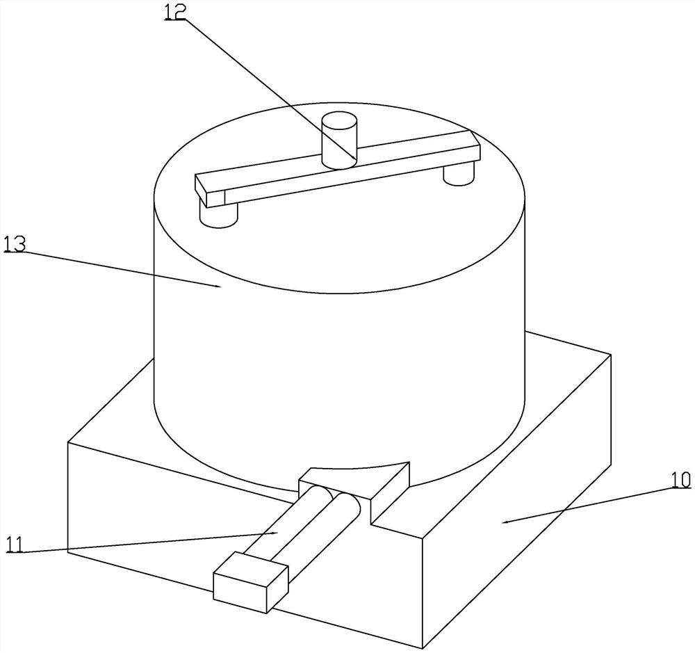
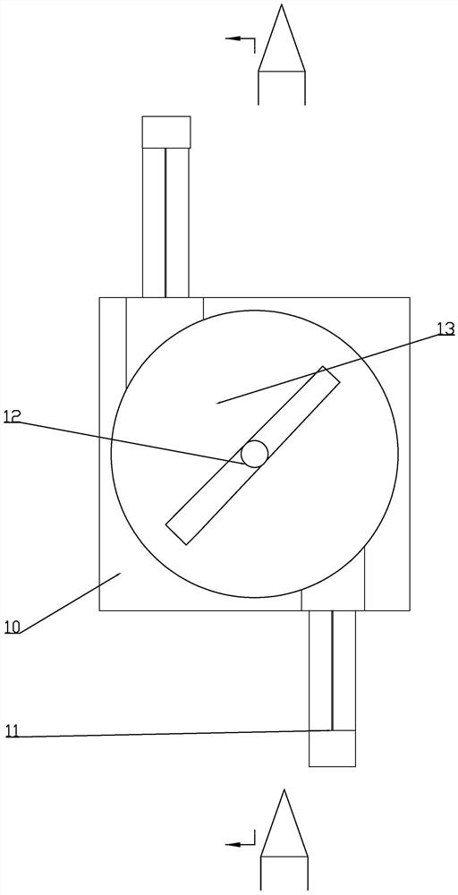
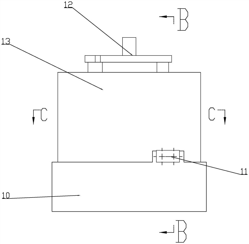
The invention relates to the technical field of boiler cleaning equipment, in particular to an automatic cleaning device for boiler scale. Comprising a base, a working shell is arranged on the upper side of the base, symmetrical water pipes are arranged on the two sides of the working shell, a water inlet and outlet pipe is fixedly connected to the side, away from the working shell, of each working shell, a cleaning component is arranged in each working shell, and a dissolving and recycling component is arranged on the side, close to the base, of each cleaning component; a combustion mechanism is arranged in the working shell, and a cleaning and transferring mechanism is arranged on the outer side of the combustion mechanism. An exhaust mechanism is arranged on the side, away from the base, of the working shell. According to the boiler, scale in the boiler and water pipes of the boiler can be cleaned during working, water is heated faster due to the large contact area with water during heating, water inlet and water outlet cannot be affected, the surface state of the combustion mechanism is detected in real time, explosion caused by expansion generated by overheating in the combustion chamber is prevented, and the service life of the combustion chamber is prolonged. And through the design of the exhaust holes, water vapor explosion is prevented, and the later-stage cost is greatly reduced.

Description

technical field [0001] The invention relates to the technical field of boiler cleaning equipment, in particular to an automatic boiler scale removal device Background technique [0002] The boiler is a kind of energy conversion equipment. The energy input to the boiler includes chemical energy and electric energy in the fuel. The boiler outputs steam, high-temperature water or organic heat carrier with a certain amount of heat energy. The original meaning of the pot refers to the water container heated on the fire. Furnace refers to the place where fuel is burned. The boiler includes two parts: the boiler and the furnace. The hot water or steam generated in the boiler can directly provide the required heat energy for industrial production and people's life, and can also be converted into mechanical energy through a steam power device, or regenerated. The generator converts mechanical energy into electrical energy, and the boiler that provides hot water is called a hot water ...

Claims


Application Information

Patent Timeline
Patent Type & Authority Applications(China)
IPC IPC(8): F24H9/00F24H9/1836F24H9/20F24H15/36F24H15/128
CPCF24H9/0042F24H9/2035F24H9/1836
Inventor 杨君
Owner 杨君
Learn More