Battery capacity measuring circuit, and battery capacity accurate calculating method and system
A voltage measurement circuit and battery capacity technology, applied in the direction of measuring electrical variables, measuring electricity, measuring devices, etc., can solve the problems of power display jumping, power error, early shutdown, etc., to save power, accurate power indication, and solve errors. bootstrap effect
- Summary
- Abstract
- Description
- Claims
- Application Information
AI Technical Summary
Problems solved by technology
Method used
Image
Examples
Embodiment 1
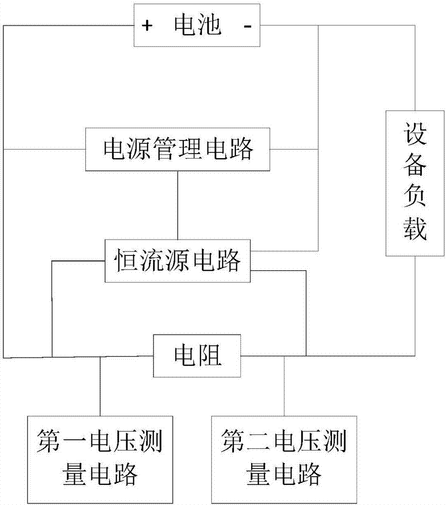
[0043] Such as figure 1 As shown, this embodiment provides a battery capacity measurement circuit, including a main circuit formed by connecting a battery, a device load, and a resistor in series, a first voltage measurement circuit connected to one end of the resistor, and a first voltage measurement circuit connected to the other end of the resistor. The second voltage measurement circuit, the first voltage measurement circuit and the second voltage measurement circuit are used to measure the terminal voltage value, and also include:
[0044] A power management circuit and a constant current source circuit, the power management circuit is connected in parallel with the battery to realize battery power supply and ensure the management work of the power management circuit; the constant current source circuit is connected in parallel with the resistor to apply a constant current to the resistor , to help the calculation of the actual resistance value; the power management circu...
Embodiment 2
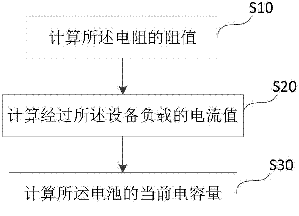
[0049] Such as figure 2 As shown, this embodiment provides a method for accurately calculating battery capacity based on the battery capacity measuring circuit described in Embodiment 1, and the method includes the following steps:
[0050] S10: Calculate the resistance value of the resistor; in this step, the resistance value (difference than the nominal value, including the resistance change caused by the production error of the solder and the resistor itself).
[0051] S20: Calculate the current value passing through the load of the device; in this step, the current value passing through the load of the device can be directly measured through the relevant electrical equipment, or the voltage difference between the two ends of the resistor can be measured first, and then divided by the actual resistance value of the resistor To obtain the current passing through the resistor, according to the theoretical knowledge of physics, the same current flows through the circuits con...
Embodiment 3
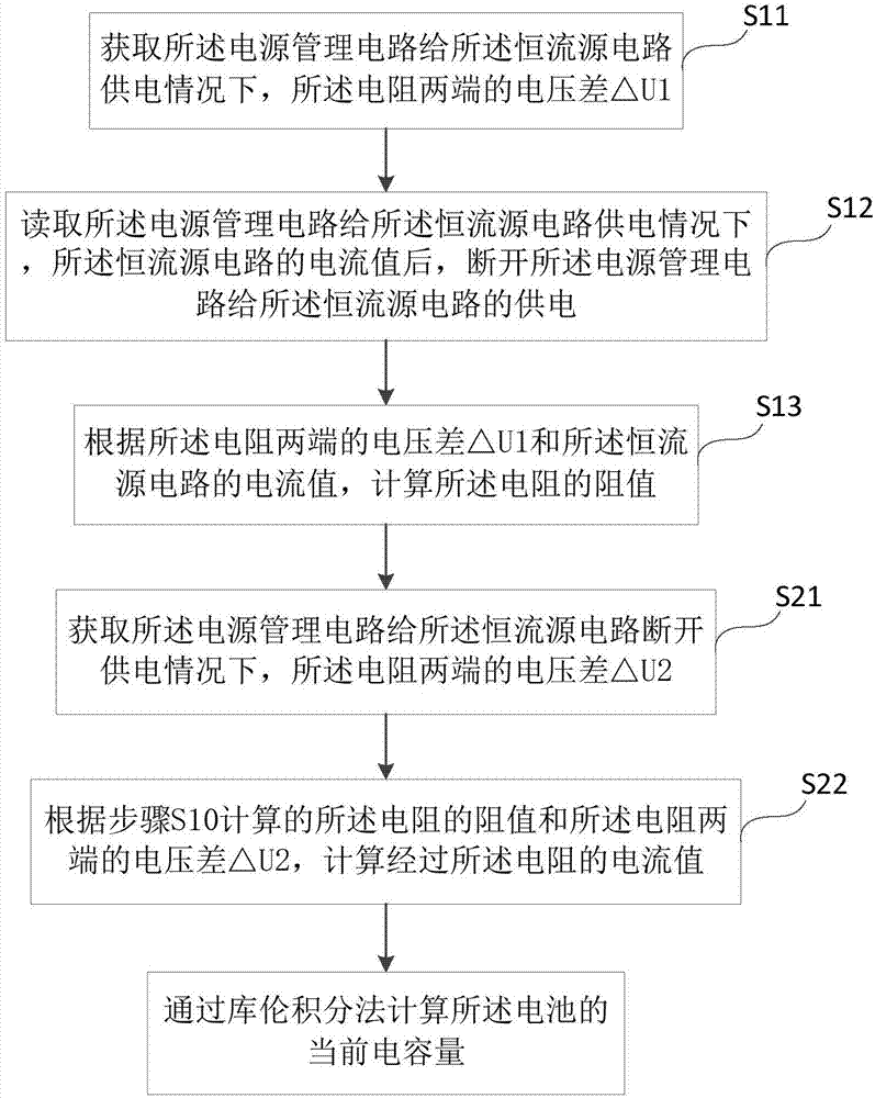
[0055] Such as image 3 As shown, the difference between this embodiment and Embodiment 2 is that this embodiment provides a more detailed method for accurately calculating battery capacity based on a battery capacity measurement circuit, and the step S10 includes:
[0056] S11: Obtain the voltage difference △U1 between the two ends of the resistor when the power management circuit supplies power to the constant current source circuit; when the terminal device is turned on, the battery is discharged, and the current is output through the positive pole, and the power management circuit receives power to work , to supply power to the constant current source circuit. At this time, the constant current source will generate a constant current and apply it to the resistor, and a voltage difference will be generated at both ends of the resistor. In this step, when the power management circuit supplies power to the constant current source circuit, through the first A voltage measureme...
PUM
 Abstract
Description
Claims
Application Information
 - R&D
- Intellectual Property
- Life Sciences
- Materials
- Tech Scout
- Unparalleled Data Quality
- Higher Quality Content
- 60% Fewer Hallucinations
Browse by: Latest US Patents, China's latest patents, Technical Efficacy Thesaurus, Application Domain, Technology Topic, Popular Technical Reports.
© 2025 PatSnap. All rights reserved.Legal|Privacy policy|Modern Slavery Act Transparency Statement|Sitemap|About US| Contact US: help@patsnap.com


