mask

A photomask and center part technology is applied in the field of photomasks for making common electrodes on array substrates, and can solve the problems of dark and bright lines in cross areas, poor display, etc.

Active Publication Date: 2020-05-05
TCL CHINA STAR OPTOELECTRONICS TECH CO LTD
View PDF5 Cites 0 Cited by
  • Summary
  • Abstract
  • Description
  • Claims
  • Application Information

AI Technical Summary

Problems solved by technology

[0003] In the pixels of the existing liquid crystal display panel, if there are intersecting common electrode lines in the display area, since extra metal is likely to appear in the intersecting area during the etching process, the intersecting area of ​​the common electrode lines forms a connection between two intersecting wires. The beveled edge (such as 45° beveled edge), so it is easy to appear dark and bright stripes in the intersection area in VA display mode, resulting in poor display

Method used


Image

  • mask
  • mask
  • mask

Examples


Embodiment Construction

[0030] The technical solutions in the embodiments of the present invention will be described below with reference to the accompanying drawings in the embodiments of the present invention. Obviously, the described embodiments are only some of the embodiments of the present invention, not all of them. Based on the embodiments of the present invention, all other embodiments obtained by persons of ordinary skill in the art without creative efforts fall within the protection scope of the present invention.

[0031] In addition, the following descriptions of the various embodiments refer to the attached drawings to illustrate specific embodiments in which the present invention can be implemented. The directional terms mentioned in the present invention, for example, "upper", "lower", "front", "rear", "left", "right", "inner", "outer", "side", etc., only is to refer to the direction of the attached drawings. Therefore, the direction terms used are for better and more clearly explaini...


PUM

PropertyMeasurementUnit
angleaaaaaaaaaa

Abstract

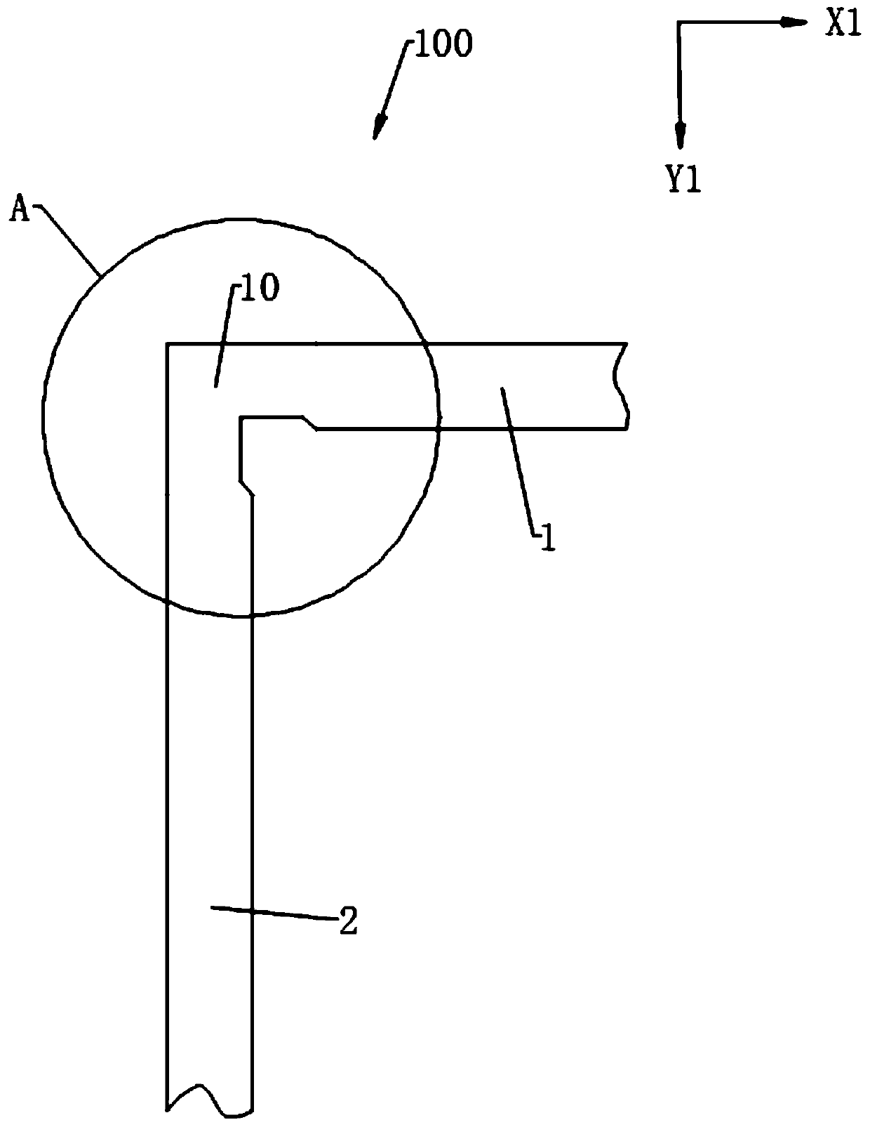
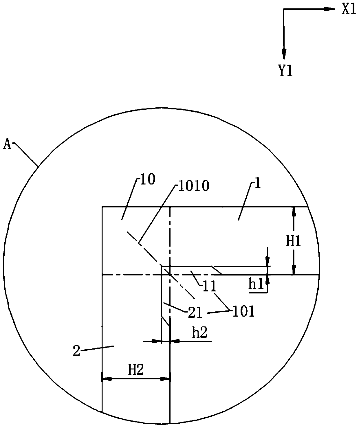
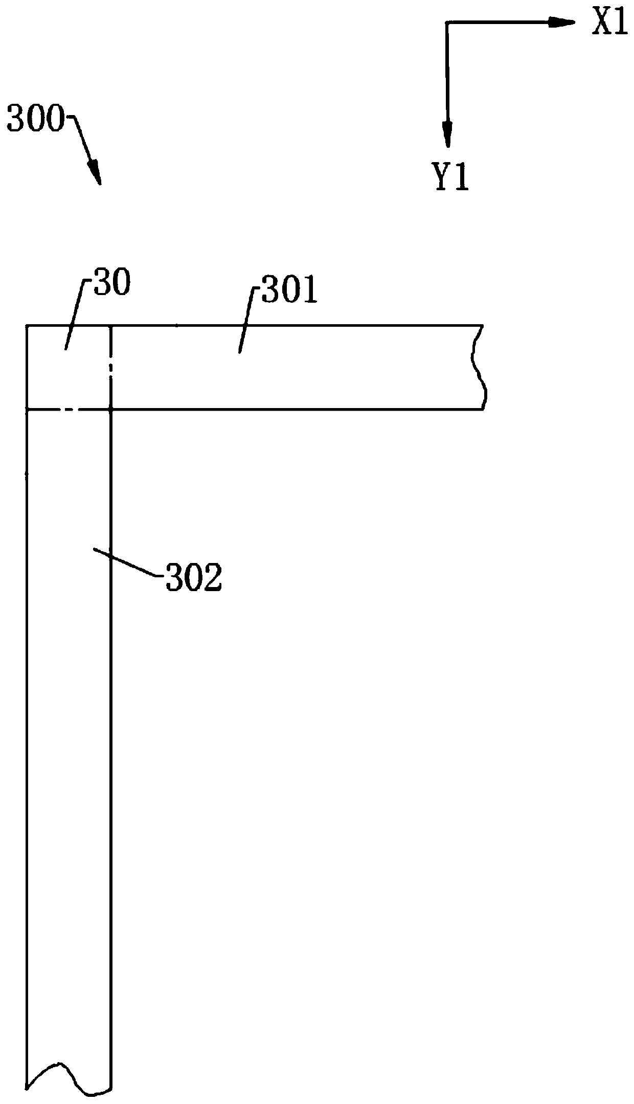
A light cover (100), used for the production of a common electrode (300) of an array substrate (200), comprising a center part (10), a first part (1) and a second part (2); the first part (1) is connected to the center part (10) and extends along a first direction (X1); the second part (2) is connected to the center part (10) and extends along a second direction (Y1); the first direction (X1) and the second direction (Y1) intersect; a first groove (11) is formed at the junction of the first part (1) and the center part (10), and a second groove (21) is formed at a junction of the second part (2) and the center part (10); and the second groove (21) is connected to the first groove (11) so as to form a first concave area (101) together. The light cover (100) may reduce the risk of poor display occurring in a liquid crystal display panel of the application array substrate (200).

Description

technical field [0001] The invention relates to the technical field of array substrate preparation, in particular to a photomask for making common electrodes on an array substrate. Background technique [0002] The liquid crystal display panel industry has experienced decades of development. The vertical alignment (VA) display mode has become a film for large-size TVs (Television, TV) due to its advantages of wide viewing angle, high contrast and no need for friction matching. A common display mode of a transistor liquid crystal display (Thin Film Transistor Liquid Crystal Display, TFT-LCD). Contrast can be measured as the ratio of the brightness of the brightest case to the brightness of the darkest case. The content of a display screen can only be displayed by the difference between pixels, and the simplest difference is light and dark. The greater the difference, the more it can be perceived by the human eye. The human pupil will zoom with the brightness of the environm...

Claims


Application Information

Patent Timeline
Patent Type & Authority Patents(China)
IPC IPC(8): G03F1/00G02F1/1343G02F1/13
CPCG02F1/1303G02F1/134309G02F1/13439G03F1/62G02F1/134318
Inventor 安立扬徐向阳
Owner TCL CHINA STAR OPTOELECTRONICS TECH CO LTD
Why Eureka
Try Eureka