Projection keyboard real time dynamic automation calibration method

A projection keyboard, real-time dynamic technology, applied in image data processing, instruments, calculations, etc., can solve the problems of inconsistent fingertip coordinate extraction, different calibration results, installation errors, etc., to eliminate different calibration results, improve calibration efficiency, and save money The effect of labor cost

Active Publication Date: 2017-12-22
哈尔滨拓博科技有限公司
View PDF5 Cites 12 Cited by
  • Summary
  • Abstract
  • Description
  • Claims
  • Application Information

AI Technical Summary

Problems solved by technology

[0002] Input devices (keyboards, mice) are important tools for human-computer interaction of computer devices or other smart devices. With the miniaturization of computer devices or wearable smart devices, many products in the electronic field will miniaturize or even miniaturize input devices. , but the smaller the input device, the trouble of inconvenient input is caused to people, but it still cannot meet the needs of mobility and portability. At present, some computer devices or wearable smart devices have adopted projection keyboards as input devices.
[0003] However, there are still many problems in the calibration of the projection keyboard. At present, manual calibration is basically used for the calibration of the projection keyboard. In the actual calibration process, manual calibration is used, and each key on the projecti

Method used


Image

  • Projection keyboard real time dynamic automation calibration method
  • Projection keyboard real time dynamic automation calibration method
  • Projection keyboard real time dynamic automation calibration method

Examples


specific Embodiment approach 1

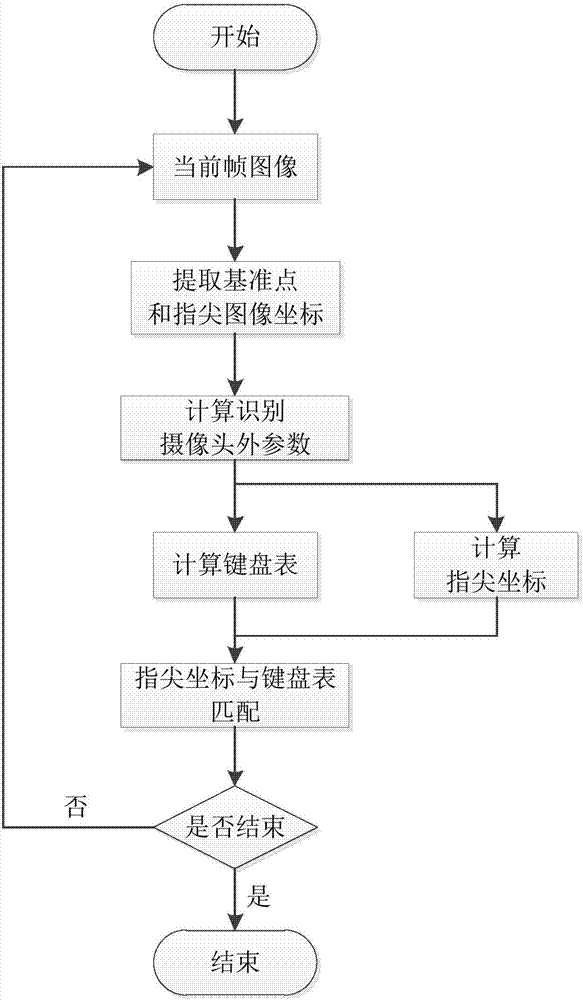
[0048] Specific implementation mode one: combine image 3 To describe this embodiment,

[0049] A real-time dynamic automatic calibration method for a projection keyboard, comprising:

[0050] Step 1. Camera calibration:

[0051] Camera calibration is the calibration of the recognition camera, which is used for fingertip area recognition and positioning;

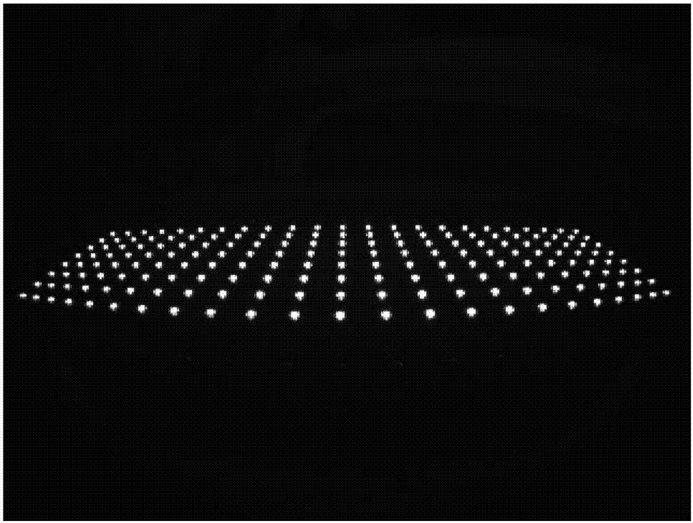
[0052] The calibration uses a customized LED small light board with known distribution size as the LED calibration board, and uses the recognition camera to take a picture of the LED calibration board, such as figure 1 As shown, the threshold segmentation algorithm is used to detect each light point on the LED calibration board, and the centroid of the light point is calculated as the coordinate of the calibration point in the image, that is, the image coordinates of the calibration point; at the same time, since the size of the LED calibration board is known, the LED The world coordinates of each light point on the calibra...

specific Embodiment approach 2

[0064] A real-time dynamic automatic calibration method for a projection keyboard, comprising:

[0065] Step 1. Camera calibration:

[0066] Camera calibration is the calibration of the recognition camera, which is used for fingertip area recognition and positioning;

[0067] The calibration uses a customized LED small light board with known distribution size as the LED calibration board, and uses the recognition camera to take a picture of the LED calibration board, such as figure 1 As shown, the threshold segmentation algorithm is used to detect each light point on the LED calibration board, and the centroid of the light point is calculated as the coordinate of the calibration point in the image, that is, the image coordinates of the calibration point; at the same time, since the size of the LED calibration board is known, the LED The world coordinates of each light point on the calibration board are known; according to the known image coordinates and world coordinates of t...

specific Embodiment approach 3

[0083] The process of calculating the world system coordinates of each button according to the overall size of the projected keyboard, the size of each button and the world coordinate system of the four calibration reference points described in step 5 of this embodiment includes the following steps:

[0084] The projected keyboard includes 6 rows of buttons and the mouse area on the right side of all the buttons; assuming that the 6 rows of buttons of the projected keyboard are respectively provided with n1, n2, n3, n4, n5 and n6 buttons, the coordinates of the buttons are calculated as follows:

[0085] Coordinate calculation of the first row of buttons:

[0086] The width of each key in the first row of n1 keys is x1, the height of the key is h1, the gap between the key levels is d1, the world coordinates of the upper left vertex of the projection keyboard are (x, y, z), and the The abscissa of the upper left vertex is (x1+d1)*(i1-1), where i1 represents the serial number of...


PUM


Abstract

A projection keyboard real time dynamic automation calibration method relates to a projection keyboard automation calibration method, and aims to solve the problems that an existing calibration method is large in calibration errors; the method comprises the following steps: using an identification camera to take a LED calibration board image, and calculating an internal parameter matrix of the camera and a distortion coefficient of a distortion model; projecting the projection keyboard on a movable plane, calibrating the relative position relation between the camera and the projection keyboard in real time, and calculating image coordinates of calibration reference points; using the projection keyboard to calculate the relative position relation between the camera and the projection keyboard and determining world coordinates of the calibration reference points; building a transformation equation of the reference points transforming from the camera coordinates to the world coordinate system according to a projection transformation relation, thus obtaining a projection transformation matrix; calculating world system coordinates of each button according to the projection keyboard sizes and the calibration reference point world coordinate system. The method is applied to the projection keyboard automation calibration.

Description

technical field [0001] The invention relates to an automatic calibration method for a projection keyboard. Background technique [0002] Input devices (keyboards, mice) are important tools for human-computer interaction of computer devices or other smart devices. With the miniaturization of computer devices or wearable smart devices, many products in the electronic field will miniaturize or even miniaturize input devices. , but the smaller the input device, the trouble of inconvenient input is caused to people, but it still cannot meet the needs of mobility and portability. At present, some computer devices or wearable smart devices have adopted projection keyboards as input devices. [0003] However, there are still many problems in the calibration of the projection keyboard. At present, manual calibration is basically used for the calibration of the projection keyboard. In the actual calibration process, manual calibration is used, and each key on the projection keyboard n...

Claims


Application Information

Patent Timeline
IPC IPC(8): G06T7/80
CPCG06T7/80
Inventor 李祝强冯大志刘璐杜国铭孙晅边文昆
Owner 哈尔滨拓博科技有限公司
Why Eureka
Try Eureka