
High-precision industrial robot tool coordinate calibration device

A technology of industrial robots and tool coordinates, applied in manufacturing tools, manipulators, program-controlled manipulators, etc., can solve problems such as affecting industrial processing quality, industrial robot processing workload, and industrial robot coordinate positioning deviation.

Inactive Publication Date: 2020-07-31
刘良斌
View PDF0 Cites 0 Cited by
  • Summary
  • Abstract
  • Description
  • Claims
  • Application Information

AI Technical Summary

Problems solved by technology

[0002] With the development and progress of the current society, the degree of intelligence in industrial production and processing is getting higher and higher. Most of the existing industrial processing uses industrial robots for refined operations, and industrial robots are mostly used in the process of refined operations. Servo motors are used to precisely locate the specific coordinates of the processing parts, but the processing workload of industrial robots is very large, and the frequency of use of servo motors is very high. With the increase of the use time of servo motors, servo motors are prone to wear and tear. The adjustment accuracy of the rotation angle changes, which makes the coordinate positioning of the industrial robot deviate, which easily affects the quality of industrial processing

Method used


Image

  • High-precision industrial robot tool coordinate calibration device
  • High-precision industrial robot tool coordinate calibration device
  • High-precision industrial robot tool coordinate calibration device

Examples


Embodiment Construction

[0012] In order to make the purpose, technical solutions and advantages of the embodiments of the present invention clearer, the technical solutions in the embodiments of the present invention will be clearly and completely described below in conjunction with the drawings in the embodiments of the present invention. Obviously, the described embodiments It is a part of embodiments of the present invention, but not all embodiments. Based on the embodiments of the present invention, all other embodiments obtained by persons of ordinary skill in the art without creative efforts fall within the protection scope of the present invention.

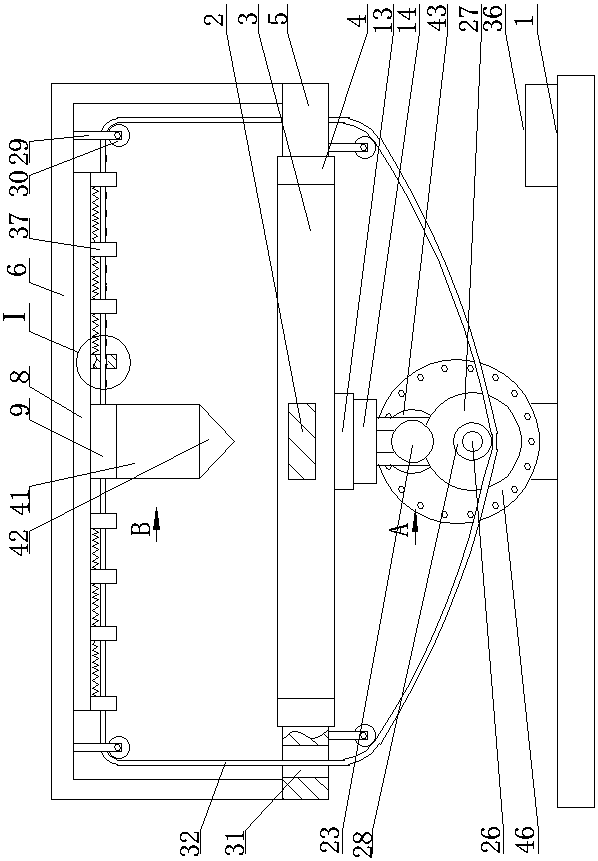
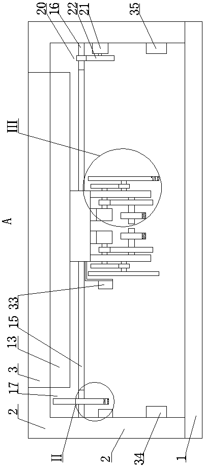
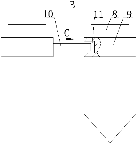
[0013]A high-precision industrial robot tool coordinate calibration device, as shown in the figure, includes a horizontal seat plate 1, the front and rear sides of the top middle of the seat plate 1 are fixed and installed with a horizontal workbench 3 through the first bracket 2, and the workbench 3 The left and right sides are respectively fixed...


PUM


Abstract

A high-precision industrial robot tool coordinate calibration device comprising a horizontal base plate, wherein a horizontal workbench is fixedly installed at the front and rear sides of the middle of the top surface of the base plate through a first bracket, first guide rails in forward and backward directions are respectively installed at left and right sides of the workbench, both the outer sides of the first guide rails are installed with first sliding blocks in slide fit with the first guide rails, an inverted U-shaped second bracket is arranged above the workbench, the bottom of the second bracket is fixedly installed with two horizontal second guide rails in forward and backward distribution, and both the lower parts of the second guide rails are provided with second sliding blocksin slide fit with the second guide rails. The invention adopts the method of matching a first servo motor and a second servo motor to complete the refined processing operation on the surfaces of theparts requiring processing, and adopts the method of matching a second laser transmitter, a third through hole and a second laser receiver to monitor the rotation angle of the first servo motor, so asto perform double and comprehensive detection on the coordinates of the entire processing device in the entire plane of the workbench to ensure the accuracy of the processing.

Description

technical field [0001] The invention belongs to the field of high-precision detection and calibration equipment, in particular to a high-precision industrial robot tool coordinate calibration device. Background technique [0002] With the development and progress of the current society, the degree of intelligence in industrial production and processing is getting higher and higher. Most of the existing industrial processing uses industrial robots for refined operations, and industrial robots are mostly used in the process of refined operations. Servo motors are used to precisely locate the specific coordinates of the processing parts, but the processing workload of industrial robots is very large, and the frequency of use of servo motors is very high. With the increase of the use time of servo motors, servo motors are prone to wear and tear. The adjustment accuracy of the rotation angle changes, which makes the coordinate positioning of the industrial robot deviate, which ea...

Claims


Application Information

Patent Timeline
IPC IPC(8): B25J9/16B25J11/00B25J19/02
CPCB25J9/1692B25J11/005B25J19/022
Inventor 刘良斌唐健豪刘德玉罗甜甜
Owner 刘良斌
Learn More