How to install the air guide

A technology of air diversion and installation method, which is applied in the direction of cooling devices, greenhouse gas reduction, climate sustainability, etc. It can solve the problems of containment cooling function failure and spray pump inoperability, so as to shorten the hoisting period and construction Cycle, the effect of improving efficiency

Active Publication Date: 2019-07-26
CHINA NUCLEAR IND FIFTH CONSTR CO LTD
View PDF5 Cites 0 Cited by
  • Summary
  • Abstract
  • Description
  • Claims
  • Application Information

AI Technical Summary

Problems solved by technology

In this way, if a power outage accident occurs, the spray pump will not work, and the containment spray system will fail to cool the containment

Method used


Image

  • How to install the air guide
  • How to install the air guide
  • How to install the air guide

Examples


Embodiment Construction

[0039] The technical solutions in the present invention will be described in detail below in conjunction with the accompanying drawings.

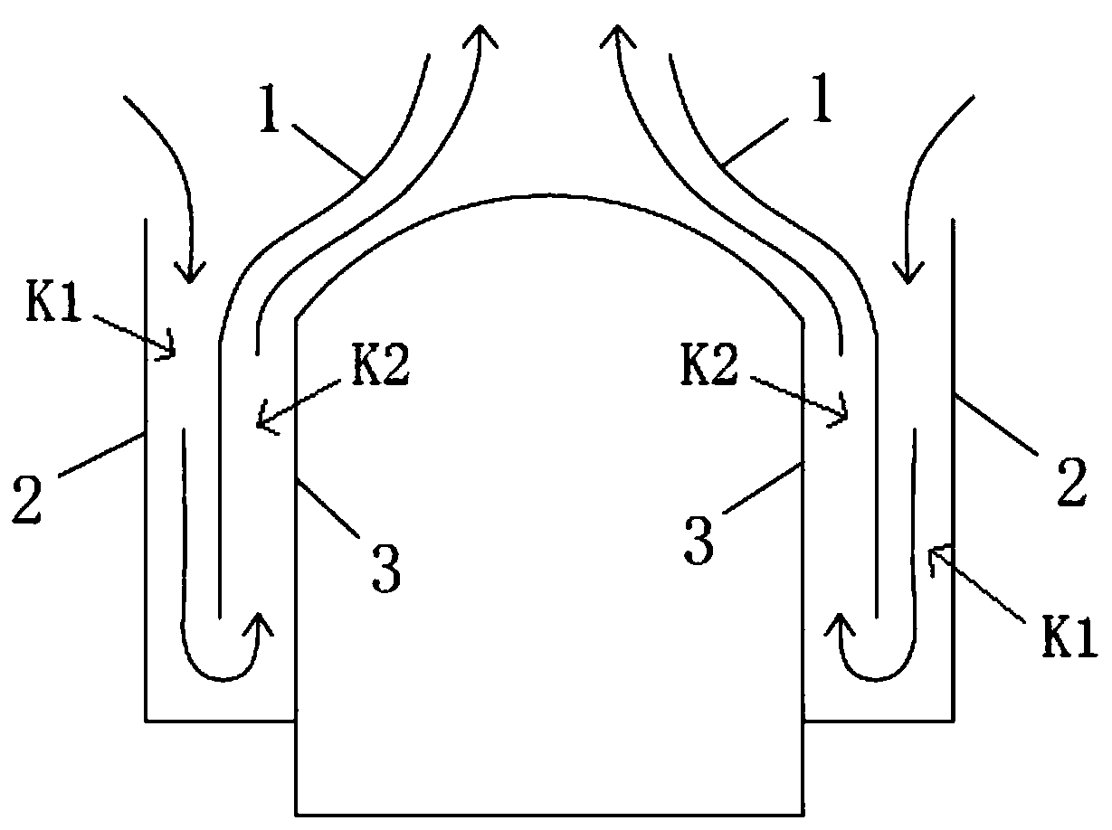
[0040] to combine figure 1 As shown, the air guiding device 1 of the present invention is an annular plate-shaped structure, located between the shielding wall 2 and the containment vessel 3, and divides the space between the shielding wall 2 and the containment vessel 3 into the shielding wall 2 and the air shielding wall connected at the bottom. The space K1 between the air guiding device 1 and the space K2 between the air guiding device 1 and the containment shell 3 , and the upper ends of these two spaces communicate with the outside atmosphere respectively.

[0041] At this time, the cold air in the outside atmosphere enters the space K1, and under the action of its own air flow and weight, the cold air flows from the upper end of the space K1 to the lower end and enters the space K2. At this time, the cold air absorbs the heat emitte...


PUM


Abstract

The invention belongs to the technical field of AP1000 nuclear power and particularly relates to an air flow guiding apparatus. The invention aims to ensure the stability of cooling operation to a containment by a containment cooling system in a nuclear power station. The air flow guiding apparatus is in an annular plate-like structure and is located between a barrier shield and the containment so as to divide the space therebetween into a space between the barrier shield and the air flow guiding apparatus and a space between the air flow guiding apparatus and the containment, bottoms of the two spaces are communicated with each other and tops are communicated with external atmosphere. By means of the air flow guiding apparatus, a boundary for guiding air flow is established between the barrier shield and the containment, so that cold air from the external atmosphere is introduced so as to remove heat, dissipated by the containment, due to flowing of air, thus achieving passive cooling to the containment. The air flow guiding apparatus not only avoids dependency on external power and saves resources, and improves reliability of cooling the containment.

Description

technical field [0001] The invention belongs to the technical field of AP1000 nuclear power, and in particular relates to an installation method of an air guiding device. Background technique [0002] In nuclear power plants, the containment cooling system is a system for cooling the containment after a reactor coolant system (RCS) loss of water accident or a rupture of the main steam pipe inside the containment. [0003] At present, the traditional PWR power plant usually implements the containment cooling function by the containment spray system. After the accident, the spray water from the refueling water tank is sprayed from the top into the air cavity of the containment by the spray pump arranged in the auxiliary building outside the containment, and the steam dispersed in it is condensed to reduce the temperature and pressure inside the containment. During the recirculation cooling phase, the spray pump is switched from the refueling tank to the recirculation pit suct...

Claims


Application Information

Patent Timeline
Patent Type & Authority Patents(China)
IPC IPC(8): G21C15/18
CPCG21C15/18Y02E30/30
Inventor 曹鑫白波李文海钱弘吴勇盛世宝宋海峰曹纪强陈林辉王建强
Owner CHINA NUCLEAR IND FIFTH CONSTR CO LTD
Why Eureka
Try Eureka