Novel rotor press plate structure

A pressure plate and rotor technology, which is applied in the field of new rotor pressure plate structure, can solve the problems of high operation requirements, high labor operation requirements and high processing costs, and achieves the effect of low personnel operation ability requirements, simplified installation procedures and high safety factor.

Pending Publication Date: 2017-12-22
HEFEI JUYI POWER SYST CO LTD
View PDF4 Cites 0 Cited by
  • Summary
  • Abstract
  • Description
  • Claims
  • Application Information

AI Technical Summary

Problems solved by technology

[0009] 1. The cost is high, the thickness of the cast aluminum plate is large, the cost is high, the strength of the machined steel plate is low, and the processing cost is high;
[0010] 2. The installation process of the pressure plate is complicated, the rotor needs to be heated and welded, and the stress is relieved after welding, the cycle is long and the efficiency is low;
[0011] 3. Heating and welding have high requirements for personnel operation. After heating, parts are easy to cause burns to personnel operation, and welding requires high operation requirements for workers, including welding size, welding position, etc., which are difficult to ensure consistency

Method used


Image

  • Novel rotor press plate structure
  • Novel rotor press plate structure
  • Novel rotor press plate structure

Examples


Embodiment Construction

[0027] The novel rotor press plate structure of the present invention adopts the sheet metal manufacturing process, and the materials can be non-magnetic isolation materials such as spcc and Q345.

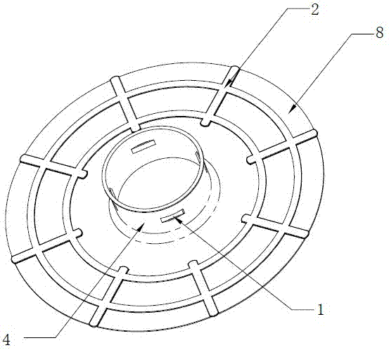
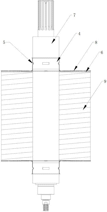
[0028] Such as Figure 1-3 As shown, the novel rotor pressure plate structure of the present invention includes a pressure plate body 8, a shaft hole is provided at the center of the pressure plate body, and a cylindrical surface 4 integrally formed with the pressure plate body and vertically upward is provided on the circumference of the shaft hole. 7 passes through it to increase the contact area.

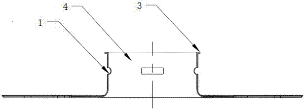
[0029] The upper end of the cylindrical surface 4 is provided with an outer flanging structure 3 to increase the strength, and the upper surface of the pressure plate body 8 is provided with raised ribs 2 .

[0030] The middle part of the cylindrical surface 4 is provided with a riveting protrusion 1 that cooperates with the rotor shaft 7 through a riveting process, and a riveting sl...


PUM


Abstract

The invention discloses a novel rotor press plate structure, which comprises a press plate body. The center of the press plate body is equipped with a shaft hole. A cylindrical surface, which is integrally formed with the press plate body, is arranged on the circumference of the shaft hole. The upper end of the cylindrical surface is provided with a flanging structure. The middle of the cylindrical surface is provided with punching and riveting protrusions that fit a rotor rotating shaft through punching and riveting. Punching and riveting clamping grooves are arranged in corresponding positions of the rotor rotating shaft. When the press plate body and a rotor are assembled, a magnetic separation thin plate is additionally arranged between the press plate body and a rotor iron core. The cylindrical surface and the rotor rotating shaft are cooperated and mounted through a punching and riveting structure, press mounting can be directly carried out in a cold condition, mounting procedures are simplified and the efficiency is high through cooperation and fixation between punching and riveting convex grooves and concave grooves, and quantitative production is suitable. Compared with a heating and welding solution, the solution of the invention has the advantages that safety coefficients are higher and requirements on operating skills of people are relatively low. In addition, a sheet metal machining process is adopted, parts can be molded easily, walls of materials are thin, the cost is low, and the weight and the dynamic balance of the rotor can be reduced.

Description

technical field [0001] The invention relates to a permanent magnet motor, in particular to a novel rotor pressing plate structure. Background technique [0002] With the development of permanent magnet motors, especially the promotion and application of permanent magnet motors in the field of electric vehicles, permanent magnet motors are highly recognized for their advantages of high power density and high efficiency, and are widely used in the field of electric vehicles. Because the permanent magnet motor is an industry that has developed rapidly in recent years, many processes need to be improved, such as the processing of the rotor. [0003] Automobile motors have relatively large power and high performance requirements. The corresponding rotor core stack thickness is relatively large. In order to reduce temperature rise and eddy current loss, the thickness of the rotor stamping stack must be thinner. In order to prevent the iron core from warping and magnetic isolation,...

Claims


Application Information

Patent Timeline
Patent Type & Authority Applications(China)
IPC IPC(8): H02K1/22H02K15/02
CPCH02K1/22H02K15/02
Inventor 刘蕾完颜亮亮汪志强
Owner HEFEI JUYI POWER SYST CO LTD
Why Eureka
Try Eureka