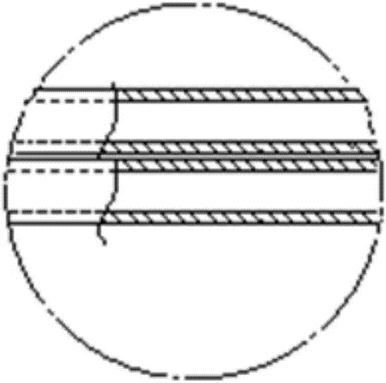
Multi-cavity ureter support
A technology for ureters and straight tubes, applied in the field of multi-lumen ureteral stents, can solve problems such as poor drainage effect of single-lumen ureteral stents, achieve the effect of treating ureter-related diseases, improving patency and safety
- Summary
- Abstract
- Description
- Claims
- Application Information
AI Technical Summary
Problems solved by technology
Method used
Image
Examples
Embodiment 1
[0032] In this embodiment, the centerline of the second straight pipe 5 is parallel to the centerline of the first straight pipe 4, the inner diameter of the second straight pipe 5 is the same as the inner diameter of the first straight pipe 4, and the wall thickness of the second straight pipe 5 Same as the wall thickness of the first straight pipe 4, the outer wall of the second straight pipe 5 is connected with the outer wall of the first straight pipe 4, such as Figure 4 Shown.
[0033] The straight pipe section 2 contains an independent second straight pipe 5. The distance between the center line of the second straight pipe 5 and the center line of the first straight pipe 4 is equal to the outer diameter of the first straight pipe 4. The cross-section of the straight pipe section 2 A figure of eight.
Embodiment 2
[0035] This embodiment is an improvement of the first embodiment.
[0036] In this embodiment, the straight pipe section 2 also contains an independent third straight pipe 6, that is, the third straight pipe 6 is a pipe independent of the second straight pipe 5 and the first straight pipe 4, and the third straight pipe 6 is located outside the first straight pipe 4 and the second straight pipe 5. The outer wall of the third straight pipe 6 is connected with the outer wall of the first straight pipe 4 and the outer wall of the second straight pipe 5. The distance from the centerline of the straight tube 4 to the centerline of the second straight tube 5 is the same, such as Figure 5 Shown.
[0037] The remaining technical features in this embodiment are the same as those in Embodiment 1. In order to save space, the present invention will not be described in detail.
Embodiment 3
[0039] This embodiment is an improvement of Embodiment 1.
[0040] In this embodiment, the straight pipe section 2 also contains two independent third straight pipes 6, the third straight pipe 6 is located outside the first straight pipe 4 and the second straight pipe 5, the outer wall of the third straight pipe 6 and the first straight pipe 6 The outer wall of the straight pipe 4 is connected with the outer wall of the second straight pipe 5. The two third straight pipes 6 are mirror images of each other about the center line of the first straight pipe 4 and the center line of the second straight pipe 5. The distance from the centerline of the third straight tube 6 to the centerline of the first straight tube 4 is the same as the distance from the centerline of the second straight tube 5, such as Image 6 Shown.
[0041] The remaining technical features in this embodiment are the same as those of Embodiment 1. In order to save space, the present invention will not be described in ...
PUM
 Abstract
Description
Claims
Application Information
 - R&D
- Intellectual Property
- Life Sciences
- Materials
- Tech Scout
- Unparalleled Data Quality
- Higher Quality Content
- 60% Fewer Hallucinations
Browse by: Latest US Patents, China's latest patents, Technical Efficacy Thesaurus, Application Domain, Technology Topic, Popular Technical Reports.
© 2025 PatSnap. All rights reserved.Legal|Privacy policy|Modern Slavery Act Transparency Statement|Sitemap|About US| Contact US: help@patsnap.com


