
Negative pressure cooling device for automobile injection molded parts

A technology for cooling devices and injection molded parts, which is applied in the field of negative pressure cooling devices for automotive injection molded parts. It can solve the problems of less air flow in the cooling chamber, low cooling efficiency, and heat up and down, so as to improve cooling efficiency and shorten cooling time. Effect

Active Publication Date: 2019-04-09
JIANGSU ZHENBAO SWITCHING EQUIP
View PDF1 Cites 0 Cited by
  • Summary
  • Abstract
  • Description
  • Claims
  • Application Information

AI Technical Summary

Problems solved by technology

[0004] The above scheme achieves rapid cooling of injection molded parts through the setting of the cooling chamber, but this device still has the following problems: During the cooling process, since the bottom of the parts is always in contact with the conveyor belt, and the air flow in the cooling chamber is less Therefore, it is impossible to cool the part where the cold part is in contact with the conveyor belt, and eventually it will form a state where the top is cool and the bottom is hot, and it is necessary to cool down the lower part of the cold part, and the cooling efficiency is still not high

Method used


Image

  • Negative pressure cooling device for automobile injection molded parts

Examples


Embodiment Construction

[0015] The present invention will be described in further detail below by means of specific embodiments:

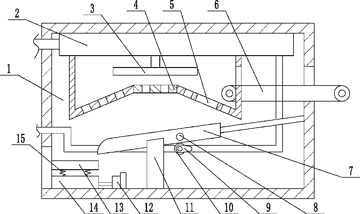
[0016] The reference signs in the drawings of the description include: cooling box 1, cooling water pipe 2, negative pressure vane 3, negative pressure cover 4, discharge port 5, belt conveyor 6, guide plate 7, swing rod 8, cam 9, Second turbine 10, support frame 11, cylinder 12, elastic rubber plate 13, base 14, stage clip 15.

[0017] Example basic reference figure 1 As shown, the negative pressure cooling device for automobile injection molded parts includes a cooling box 1. A cooling water pipe 2 is fixed in the cooling box 1 through a clamp. A belt conveyor 6 is arranged at the entrance of the cooling box 1. There is a first turbine, and the first turbine is coaxially connected with a negative pressure blade 3 located outside the cooling water pipe 2. A negative pressure cover 4 is arranged in the cooling box 1, and the negative pressure blade 3 is arranged in the n...


PUM


Abstract

The invention discloses a negative-pressure type cooling device for automobile injection molding parts. The negative-pressure type cooling device comprises a cooling box; a cooling water pipe is fixed in the cooling box; a conveying belt is arranged at an inlet of the cooling box; a first turbine is rotatably connected in the cooling water pipe; the first turbine and a negative-pressure blade are coaxially connected; a negative-pressure cover is arranged in the cooling box; the negative-pressure blade is arranged in the negative-pressure cover; a feeding inlet and a discharging outlet are formed in the negative-pressure cover; an inclined guide plate is arranged below the negative-pressure cover; a negative-pressure hole is formed in the negative-pressure cover; an arc-shaped groove is formed in one side of the guide plate; the guide plate is rotatably connected in the cooling box; a swinging rod is fixed to the guide plate; a second turbine is rotatably connected in the cooling water pipe; the second turbine and a cam are connected coaxially; the cam abuts against the swinging rod; and a buffering mechanism is slidably connected to an outlet of the cooling box and located below the guide plate. Compared with the prior art, by arranging the negative-pressure blade, the negative-pressure cover, the guide plate, the cam and the like, the cooling time is greatly shortened, and the cooling efficiency is improved.

Description

technical field [0001] The invention relates to the technical field of auto parts production equipment, in particular to a negative pressure cooling device for auto injection molded parts. Background technique [0002] Many of the existing auto parts are formed by injection molding. The injection molding parts are formed by the injection molding machine and then taken out of the mold. After demoulding, the temperature is relatively high, generally around 60°C. It needs to be cooled before it can be processed. A production process, and if it is placed in the air to cool naturally, but natural cooling takes a lot of time and affects production efficiency. [0003] In order to solve the above problems, the invention patent with the Chinese patent application number 201510347907.X discloses a cooling device for automotive injection molding parts, which includes a box-like structure composed of two vertical plates on the left and right and two horizontal plates on the upper and l...

Claims


Application Information

Patent Timeline
Patent Type & Authority Patents(China)
IPC IPC(8): B29C45/72
CPCB29C45/7207
Inventor 杨娟
Owner JIANGSU ZHENBAO SWITCHING EQUIP
Learn More