Pump body assembly and compressor with pump body assembly
A component and pump body technology, which is applied to pump components, liquid fuel engines, components of pumping devices for elastic fluids, etc. Improves operational reliability, improves performance, and prevents wear and tear
- Summary
- Abstract
- Description
- Claims
- Application Information
AI Technical Summary
Problems solved by technology
Method used
Image

Examples
Embodiment 1
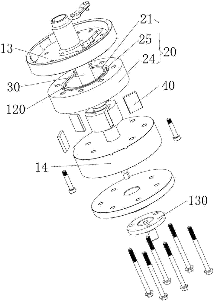
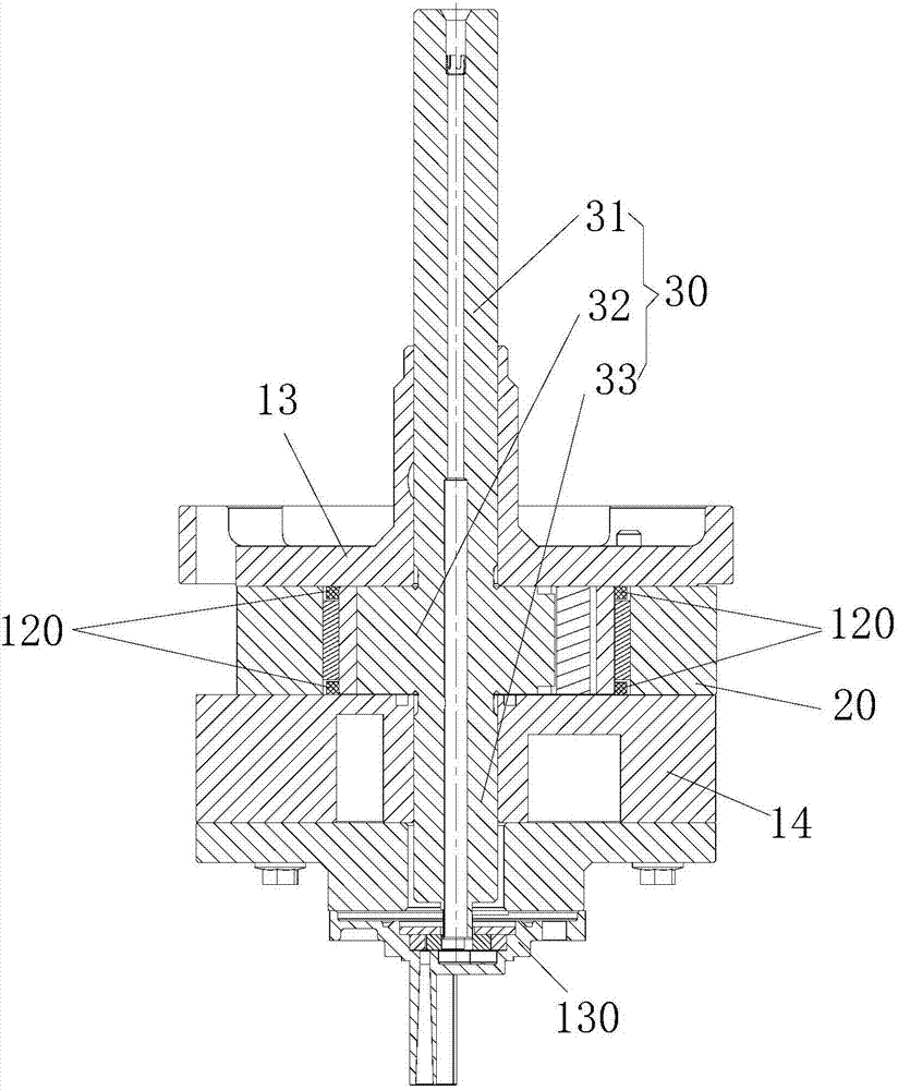
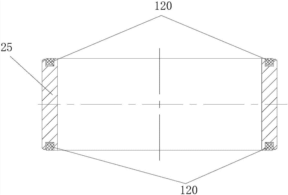
[0048] Such as Figure 1 to Figure 6 As shown, the pump body assembly includes a structural member, a bearing cylinder 20 and at least one anti-friction structure 120. Among them, there are two structural parts. The bearing-type cylinder 20 is arranged between two structural parts. The bearing-type cylinder 20 includes an outer ring 24 and an inner ring 25 capable of rotating relative to the outer ring 24. At least one anti-friction structure 120 is provided on at least one end surface of the inner ring 25 facing the structural member to reduce the friction between the bearing cylinder 20 and the structural member.
[0049] The anti-friction structure 120 is arranged on the end surface of the inner ring 25 facing the structural member, so that no contact friction occurs between the inner ring 25 of the bearing cylinder 20 and the structural member.
[0050] During the operation of the pump body assembly, the inner ring 25 can rotate relative to the outer ring 24. Even if the inner...
Embodiment 2
[0073] The difference between the pump body assembly of the second embodiment and the first embodiment is that the structure of the friction reducing structure 120 is different.
[0074] Such as Figure 7 As shown, part or all of the end surface of the antifriction structure 120 away from the structure is provided with a protruding structure 121, and the end surface of the protruding structure 121 away from the structure is in contact with the bottom of the limiting ring groove 141. In this way, in the process of assembling the anti-friction structure 120 and the limiting ring groove 141, the protruding structure 121 can abut against the bottom of the limiting ring groove 141, and then the anti-friction structure 120 is assembled in an appropriate position, namely When the pump body assembly is not turned on or under the action of the mixture of high-pressure refrigerating machine oil and refrigerant, the antifriction structure 120 can be attached to the upper and lower flanges.
...
Embodiment 3
[0080] The difference between the pump body assembly of the third embodiment and the first embodiment is that the structure of the limiting part is different.
[0081] Such as Figure 8 to Figure 10 As shown, the limit part is a limit boss 142, and the antifriction structure 120 is a ring structure. The ring structure is sleeved on the limit boss 142 and the two have an interference fit. Part or all of the antifriction structure 120 is far away There is an axial gap 150 between the end surface of the structural member and the end surface of the inner ring 25 facing the structural member. In this way, the above arrangement can not only ensure that the surface of the antifriction structure 120 on the side away from the rolling element accommodating cavity 21 closely fits with the stop ring groove 141, but also ensure that the mixture of high-pressure refrigerating machine oil and refrigerant can enter the antifriction structure 120 far away The friction reducing structure 120 is p...
PUM
 Abstract
Description
Claims
Application Information
 - R&D
- Intellectual Property
- Life Sciences
- Materials
- Tech Scout
- Unparalleled Data Quality
- Higher Quality Content
- 60% Fewer Hallucinations
Browse by: Latest US Patents, China's latest patents, Technical Efficacy Thesaurus, Application Domain, Technology Topic, Popular Technical Reports.
© 2025 PatSnap. All rights reserved.Legal|Privacy policy|Modern Slavery Act Transparency Statement|Sitemap|About US| Contact US: help@patsnap.com