Bulb with self-forming LED light source

A LED light source and self-forming technology, applied in the direction of light source, slender light source, light source fixation, etc., can solve the problems of reduced processing efficiency, complicated installation process, and increased cost, so as to improve processing efficiency, simplify internal structure, and increase heat dissipation performance Effect

Inactive Publication Date: 2017-12-26
ZHEJIANG EMITTING OPTOELECTRONICS TECH
View PDF2 Cites 3 Cited by
  • Summary
  • Abstract
  • Description
  • Claims
  • Application Information

AI Technical Summary

Problems solved by technology

However, in actual use, it is also found that since the spiral filament is a flexible filament, after it is installed in the bulb, it needs a support structure to fix its position in the bulb. At present, the more common ones are horizontal, vertical, and oblique glass wick columns. The combination of the supporting structure and the metal connecting wire (such as tungsten wire) fixed on the glass wick column is used to fix the flexible filament, resulting in an overly complicated internal structure of the bulb, complicated installation process, increased installation cost, and reduced processing efficiency
[0003] Along with the increase in wattage, another problem also follows---that is, the problem of heat dissipation. At present, there are usually two ways to dissipate heat for LED bulbs. One is to add heat dissipation gas, and the other is to install heat pipes to achieve heat dissipation. For example, in the patent No. 201210063705.9 (a kind of LED light bulb) applied by Zhejiang Ruidison Optoelectronics Co., Ltd. on 12th, 2012, it stated that "the LED light source is composed of at least one transparent LED light-emitting column; the LED light-emitting column Including: a high thermal conductivity transparent tube inserted on the outer surface of the pillar”; in the two ways, the former leads to complicated processing technology, and the latter leads to complicated structure, which in turn leads to increased costs

Method used


Image

  • Bulb with self-forming LED light source
  • Bulb with self-forming LED light source
  • Bulb with self-forming LED light source

Examples


Embodiment Construction

[0034] The present invention will be further described in detail below in conjunction with the drawings and specific embodiments.

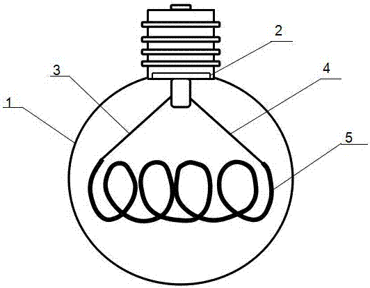
[0035] by figure 1 It can be seen that a light bulb with a self-forming LED light source includes a light bulb shell 1 made of transparent or partially transparent glass, with any shape, inflated or not inflated inside, and a power driver 2 is provided at the back of the bulb shell 1. The power supply positive pole 3 and the power negative pole 4 are provided at both ends of the power driver 2, and also includes a self-forming LED light source arranged in the bulb shell in a horizontal, vertical or diagonal direction. The two ends of the self-forming LED light source The positive pole and negative pole of the power supply are respectively provided. The positive pole and the negative pole of the power supply are electrically connected with the positive pole 3 of the power supply and the negative pole 4 of the power supply. The so-called electrical conn...


PUM


Abstract

The invention discloses a bulb with a self-forming LED light source. The bulb comprises a bulb shell. The bulb shell is made of transparent or locally transparent glass, is in an arbitrary shape and is internally inflated or not inflated. A power source drive is arranged at the rear end of the bulb shell. A power source positive-pole electric rod and a power source negative-pole electric rod are arranged at the two ends of the power source drive. The bulb further comprises the self-forming LED light source arranged in the bulb shell transversely, or vertically or obliquely. A positive pole and a negative pole are arranged at the two ends of the self-forming LED light source correspondingly and electrically connected with the power source positive-pole electric rod and the power source negative-pole electric rod correspondingly. An original supporting structure for supporting an LED flexible lamp filament in the bulb is omitted, so that the internal structure of the bulb is simplified greatly, the machining efficiency is improved, and the manufacturing cost is reduced. By adopting the structure that the flexible lamp filament or flexible lamp slices are attached to the inner wall of the bulb, the heat dissipation performance of the bulb shell of the bulb is optimized, and accordingly the overall heat dissipation performance of the bulb is improved.

Description

Technical field [0001] The invention relates to the field of lighting lamps, in particular to a bulb with a self-forming LED light source, belonging to the technical field of LED lighting. Background technique [0002] The LED light source has sufficient brightness, uniform light emission, and low power consumption, which can be called green energy. Therefore, it has gradually replaced the tungsten filament lamp that has been used for hundreds of years. With the further development of lighting technology, the LED light source has gradually evolved from a point light source. Become a strip light source, even a long strip of flexible filaments of various shapes; LED flexible filaments can increase the wattage by many times or even several times in the same area, and have strong practicality. This is a traditional strip. The spiral-shaped LED flexible filament is currently more common, which has a beautiful structure and large luminous wattage. However, it has also been found in ac...

Claims


Application Information

Patent Timeline
Patent Type & Authority Applications(China)
IPC IPC(8): F21K9/232F21K9/64F21V19/00F21V29/503F21Y115/10
CPCF21V29/503F21K9/64F21K9/232F21V19/0025F21Y2115/10F21Y2103/30H01L25/0753F21K9/23F21K9/238F21K9/237
Inventor 李杨邹军李文博
Owner ZHEJIANG EMITTING OPTOELECTRONICS TECH
Why Eureka
Try Eureka