Motor control loop power supply mode

A power supply mode and motor control technology, which is applied to circuit devices, electrical components, emergency power supply arrangements, etc., can solve problems such as unusable, control power fluctuations, and motor inoperability, and achieve the effect of simple scheme, easy implementation, and cost control

Inactive Publication Date: 2017-12-26
鞍钢集团工程技术有限公司
View PDF7 Cites 2 Cited by
  • Summary
  • Abstract
  • Description
  • Claims
  • Application Information

AI Technical Summary

Problems solved by technology

[0004] Table 1 Disadvantages of the two motor control loop power supply methods
[0005] Motor control circuit power supply mode: shortcoming: Directly from the common bus It cannot be used in the IT grounding system, and the control power is prone to fluctuations Add a control transformer in the receiving cabinet Unable to provide stable control power for Class I and Class II motor loads
[0009] However, the power supply mode of the traditional control loop cannot meet the power supply needs of the first and second loads in the grounding system. The control loop of the traditional IT system cannot meet the switching of the backup security power supply because the control transformer is installed in the power receiving cabinet. In the IT grounding system, when the control circuit loses power, even if the main circuit of the motor has been put into the backup power supply, the motor still cannot run, which seriously affects the safe operation of the equipment

Method used


Image

  • Motor control loop power supply mode
  • Motor control loop power supply mode
  • Motor control loop power supply mode

Examples


Embodiment Construction

[0026] The specific embodiments provided by the present invention will be described in detail below in conjunction with the accompanying drawings.

[0027] A power supply mode for a motor control circuit, in which a dedicated control transformer is installed at the outlet of a dual-way power transfer switch in a feeder cabinet.

[0028] The two-way power conversion switch is connected to two power sources, one power source is drawn from the original motor control cabinet common bus, and the other power source is from a security power supply device such as a diesel generator. When the first power supply stops working, the security The power supply is immediately put into use, thereby ensuring the safe power supply of the first and second class motor loads.

[0029] 【Example】

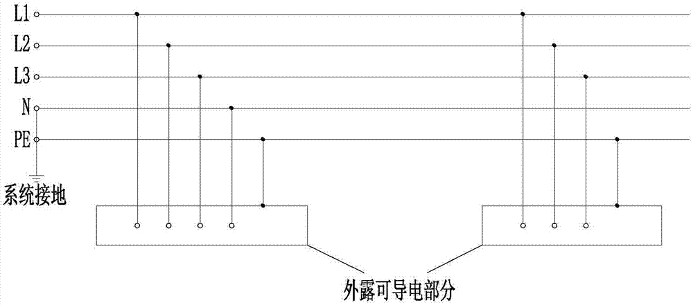
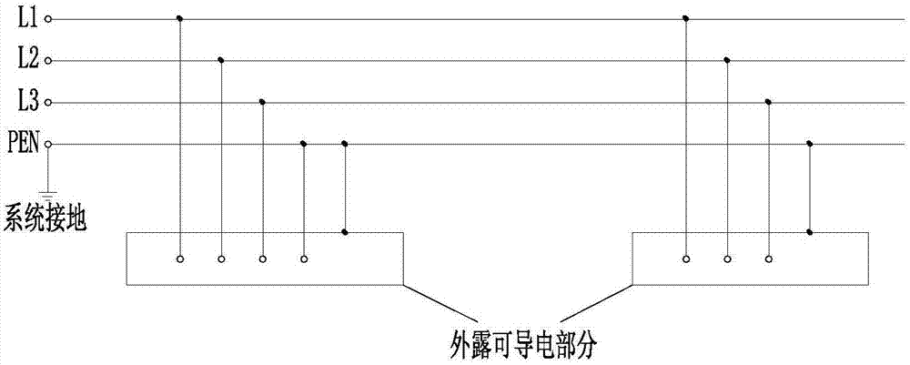
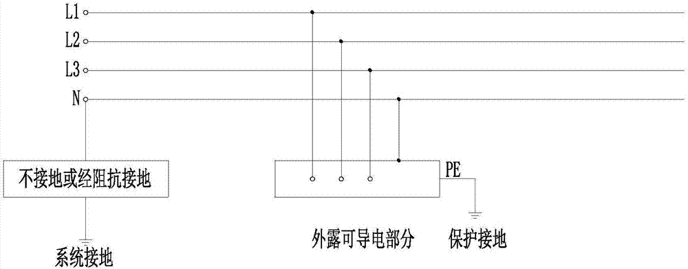
[0030] Panzhihua Iron and Steel Xichang Cold Rolling Project continuous withdrawal unit, a new set of motor control cabinets, powered by a transformer, grounding type for the IT system. Some of the load...


PUM


Abstract

The invention provides a motor control loop power supply mode. According to the motor control loop power supply mode, a special control transformer is arranged at the wire outlet of a two-way power conversion switch inside a feed cabinet, wherein the two-way power conversion switch is connected to two power sources, one power source is the common bus of an existing motor control cabinet, the other power source is an emergency power supply device such as a diesel generator, and when the first power source stops working, the emergency power supply device can be put into service instantly to further ensure emergency power supply of type I and II motor loads. Together with a main loop, the special control transformer achieves power switch control and is always powered by one power source. Therefore, the motor control loop power supply mode is applicable to various grounding systems, effectively solves the problem of fluctuation of control power sources, ensures reliability of the power sources of the control transformer and further ensures reliability of a motor control loop power source of an entire system.

Description

technical field [0001] The invention relates to the technical field of low-voltage power distribution, in particular to a power supply mode for a motor control loop. Background technique [0002] In the low-voltage grounding system, when the grounding system is a TN system, one point of the power supply end is directly grounded (usually the neutral point), and the exposed conductive part of the electrical device is connected to this grounding point through a protective neutral conductor or a protective conductor. According to the combination of the neutral conductor and the protective conductor, the TN system has two situations: the TN-S system and the TN-C system, such as figure 1 , figure 2 shown. The TN system can directly provide N-phase, and then provide AC220V control power. However, not all places are suitable for TN systems. For places with high requirements for uninterrupted power supply and strict restrictions on ground fault voltage, IT grounding systems are s...

Claims


Application Information

Patent Timeline
Patent Type & Authority Applications(China)
IPC IPC(8): H02J9/06H02J3/24
CPCH02J3/24H02J9/066
Inventor 许伟刘杰马洪峰王丽赵建东常欣宋学奎郑伟张明文
Owner 鞍钢集团工程技术有限公司
Why Eureka
Try Eureka