
Patsnap Eureka
For R&D, Patsnap Eureka makes reading and utilizing patents & technical documents easy.
Patsnap Eureka AIR
Designed for self-driven R&D workflows. Generate viable solutions, solve complex R&D challenges, empower your innovation with AI.

Patsnap Eureka Materials
Designed for material experts only. Revolutionize your material R&D, from search, analyze, to developing new materials.

TechResearch
Generate reliable direction feasibility study reports for your R&D in just a few steps.

TechSeek
Discover and master advanced knowledge NOW. Basics, ideas, possibilities, all at once.

TechMind
As an expert in R&D Theories, TechMind can generates customized viable solutions instantly.

TechRisk
Analyze your overall solution with one click, know your potential R&D risks in advance.

TechMonitor
Get weekly tech updates, stay abreast of the latest tech innovations and key insights.
Laminated glass conveying rack applied under high temperature and high pressure conditions
A laminated glass, high temperature and high pressure technology, applied in conveyor objects, furnace components, transportation and packaging, etc., can solve problems such as loss of workers, injury, poor fixing effect, etc., to avoid slipping or dumping.
- Summary
- Abstract
- Description
- Claims
- Application Information
AI Technical Summary
Problems solved by technology
Method used
Image


Examples
Embodiment 1
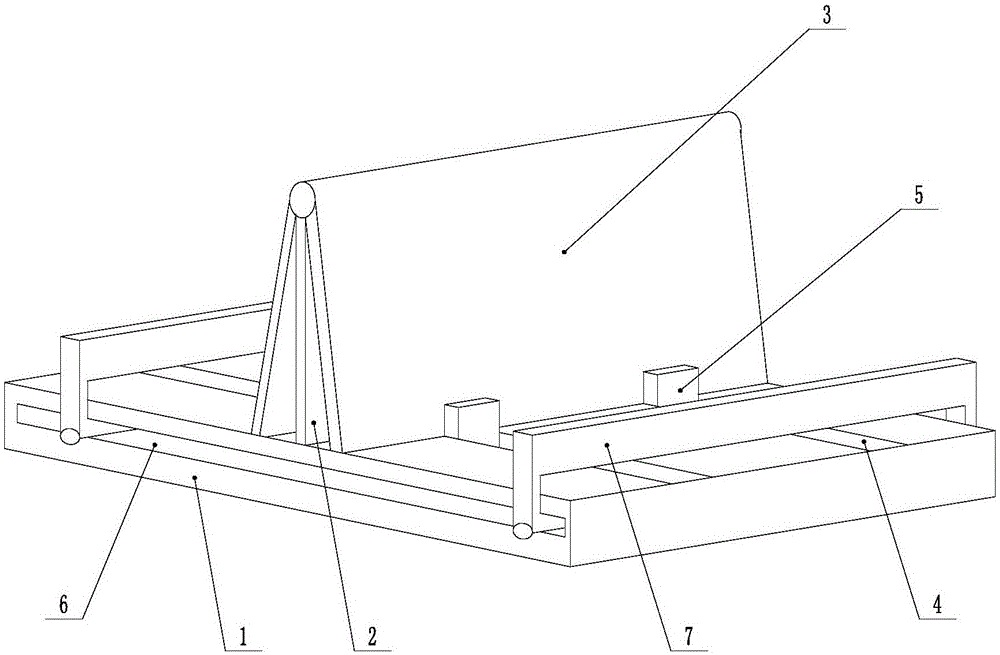
[0027] Such as figure 1 As shown, the present invention is applicable to the laminated glass delivery frame under high temperature and high pressure conditions, including a base 1, a support frame 2 is arranged on the base 1, and a placement plate 3 is arranged on both sides of the support frame 2, and the placement plate 3 can be connected with the support frame around it. The joint of 2 rotates, and the top surface of the base 1 is provided with a chute-4, and a stopper 5 is arranged in the chute-4, and the stopper 5 can move along the chute-4, and the side of the base 1 is provided with a chute Groove 2 6, the chute 2 6 is provided with a movable baffle 7, the movable baffle 7 can move along the chute 2 6, and the placement plate 3 is rotated around its connection with the support frame 2, and the laminated glass placed as required To adjust the angle between the placing plate 3 and the support frame 2, that is, the inclination angle of the placing plate 3, and then fix the...
Embodiment 2
[0029] The present invention is based on embodiment 1, and the present invention is further described.
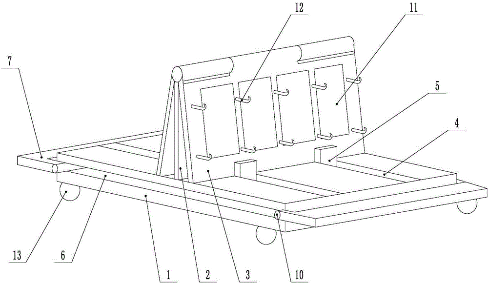
[0030] Such as Figure 1 ~ Figure 2 As shown, the present invention is applicable to the laminated glass conveying frame under high temperature and high pressure conditions. The support frame 2 and the placement plate 3 are connected by the rotating shaft 8, and the placement plate 3 can rotate around the axial direction of the rotating shaft 8. When the support frame 2 and the placement plate The top of 3 is provided with a through hole with the same diameter, and then the rotating shaft 8 is passed through the through hole, so that the placing plate 3 can rotate around the axial direction of the rotating shaft 8, and the bottom of the placing plate 3 is provided with a sliding part 9, when the placing plate 3 revolves around the rotating shaft When the axial direction of 8 rotates, the sliding part 9 moves in the chute-4, and when the placing plate 3 rotates, its bottom w...
Embodiment 3
[0032] The present invention is based on embodiment 1, and the present invention is further described.
[0033] Such asfigure 1 As shown, the present invention is applicable to the laminated glass conveying frame under high temperature and high pressure conditions, the number of chute-4 is one or several, and when the number of chute-4 is multiple, the number of corresponding stoppers 5 is also multiple , take the blocks 5 on both sides of the board 3 as a group, when the resistance and support function of one group of blocks 5 fails, the other groups of blocks 5 can continue to play the role of resistance and support, and the blocks 5 can pass through Threaded fasteners are fixed in the first chute 4, and a connecting piece 10 is arranged between the moving baffle plate 7 and the second chute 6, the connecting piece 10 is cylindrical, and the connecting piece 10 can move along the second chute 6 , and the moving baffle 7 can rotate around the axial direction of the connecting...
PUM
 Abstract
Description
Claims
Application Information
 - R&D Engineer
- R&D Manager
- IP Professional
- Industry Leading Data Capabilities
- Powerful AI technology
- Patent DNA Extraction
Browse by: Latest US Patents, China's latest patents, Technical Efficacy Thesaurus, Application Domain, Technology Topic, Popular Technical Reports.
© 2024 PatSnap. All rights reserved.Legal|Privacy policy|Modern Slavery Act Transparency Statement|Sitemap|About US| Contact US: help@patsnap.com